02 May 2013
For anyone using the Nexus 1000V virtual switch, it’s sometimes useful to see what is happening directly on the Virtual Ethernet Module (VEM) residing on the host, rather than just having visibility from the Virtual Supervisor Module (VSM). The method to achieve this is via the ‘vemcmd’ syntax on the ESXi host. Unfortunately these commands are not well documented, so I thought it would be useful to provide a list of some of the more common ones.
**vemcmd show card **- shows a multitude of information about the VEM, including the domain, switch name, ‘slot’ number, which control mode you are using (L2 or L3) and much more.
~ # <strong>vemcmd show card</strong>
Card UUID type  2: 4225e800-d334-720d-e73e-d3a8d500a201
Card name: lab.cisco.com
Switch name: N1KV
Switch alias: DvsPortset-0
Switch uuid: b6 e9 19 50 c5 4b 78 ff-c3 f3 a1 13 61 d2 8a d5
Card domain: 10
Card slot: 3
VEM Tunnel Mode: L3 Mode
L3 Ctrl Index: 49
L3 Ctrl VLAN: 666
VEM Control (AIPC) MAC: 00:02:3d:10:0a:02
VEM Packet (Inband) MAC: 00:02:3d:20:0a:02
VEM Control Agent (DPA) MAC: 00:02:3d:40:0a:02
VEM SPAN MAC: 00:02:3d:30:0a:02
Primary VSM MAC : 00:50:56:99:a7:82
Primary VSM PKT MAC : 00:50:56:99:94:df
Primary VSM MGMT MAC : 00:50:56:99:eb:a7
Standby VSM CTRL MAC : ff:ff:ff:ff:ff:ff
Management IPv4 address: 192.168.66.55
Management IPv6 address: 0000:0000:0000:0000:0000:0000:0000:0000
Primary L3 Control IPv4 address: 192.168.66.57
Secondary VSM MAC : 00:00:00:00:00:00
Secondary L3 Control IPv4 address: 0.0.0.0
Upgrade : Default
Max physical ports: 32
Max virtual ports: 300
Card control VLAN: 1
Card packet VLAN: 1
Control type multicast: No
Card Headless Mode : No
       Processors: 2
  Processor Cores: 2
Processor Sockets: 1
  Kernel Memory:   8388084
Port link-up delay: 5s
Global UUFB: DISABLED
Heartbeat Set: True
PC LB Algo: source-mac
Datapath portset event in progress : no
Licensed: Yes
vemcmd show port **- shows a list of the ports on this VEM and the VMs or VMKs connected to them.
**
~ # vemcmd show port
  LTL   VSM Port  Admin Link  State  PC-LTL  SGID  Vem Port  Type
   20     Eth3/4     UP   UP    FWD     561     3    vmnic3
   49      Veth1     UP   UP    FWD       0     3      vmk1
   50      Veth3     UP   UP    FWD       0     3      vmk2  VXLAN
   51      Veth5     UP   UP    FWD       0        Ubuntu-1.eth0
  561        Po1     UP   UP    FWD       0
**vemcmd show port vlans **- shows a list of the ports on this VEM and the VLANs associated with them.
~ # vemcmd show port vlans
                          Native  VLAN   Allowed
  LTL   VSM Port  Mode    VLAN    State* Vlans
   20     Eth3/4   T          1   FWD    1,666,800
   49      Veth1   A        666   FWD    666
   50      Veth3   A        800   FWD    800
  561        Po1   T          1   FWD    1,666,800
**vemcmd show stats **- displays some general statistics (bytes sent & received, etc) associated with each port.
~ # vemcmd show stats
 LTL  Received        Bytes      Sent        Bytes   Txflood    Rxdrop    Txdrop  Name
 8    853658    163106173   1706853    285044028    853377         0         0
 9   1706853    285044028    853658    163106173    853658         0         0
 10        16          960        42         2520        42         0         0
 12        16          960        42         2520        42         0         0
 15         0            0   3403853    806578120   1682744         0         0
 16      1661       152812         0            0         0         0         0  ar
 20  19831000   2862819019    851081    124246350       653  12789591         2  vmnic3
 49     24916      1494960   2806579    393405034   2781688         0         0  vmk1
 50    813566    119314022    832174    125090824       199         0         0  vmk2
 51    812802     78710878    831405     83473094     18639         0         0  Ubuntu-1.eth0
**vemcmd show vlan **- displays VLAN information and which port is associated with each one.
~ # vemcmd show vlan
 Number of valid VLANs: 8
 VLAN 1, vdc 1, swbd 1, hwbd 1, 4 ports
Portlist:
 VLAN 666, vdc 1, swbd 666, hwbd 7, 3 ports
Portlist:
 20  vmnic3
 49  vmk1
 561
VLAN 800, vdc 1, swbd 800, hwbd 8, 3 ports
Portlist:
 20  vmnic3
 50  vmk2
 561
VLAN 3968, vdc 1, swbd 3968, hwbd 5, 3 ports
Portlist:
 1  inban
 5  inband port securit
 11
VLAN 3969, vdc 1, swbd 3969, hwbd 4, 2 ports
Portlist:
 8
 9
VLAN 3970, vdc 1, swbd 3970, hwbd 3, 0 ports
Portlist:
 VLAN 3971, vdc 1, swbd 3971, hwbd 6, 2 ports
Portlist:
 14
 15
<strong>vemcmd  show l2 all </strong>- shows MAC address and other information for all bridge domains and VLANs.
~ # vemcmd show l2 all
 Bridge domain    1 brtmax 4096, brtcnt 6, timeout 300
 VLAN 1, swbd 1, ""
 Flags:  P - PVLAN  S - Secure  D - Drop
 Type         MAC Address   LTL   timeout   Flags    PVLAN
 Static   00:02:3d:80:0a:02     6         0
 Static   00:02:3d:40:0a:02    10         0
 Static   00:02:3d:30:0a:02     3         0
 Static   00:02:3d:60:0a:00     5         0
 Static   00:02:3d:20:0a:02    12         0
 Static   00:02:3d:10:0a:02     2         0
**vemcmd show l2 bd-name <_name_> **- shows MAC address and other information for a specific bridge domain (useful if using VXLANs).
~ # vemcmd show l2 bd-name test-vm
Bridge domain    9 brtmax 4096, brtcnt 2, timeout 300
Segment ID 5000, swbd 4096, "test-vm"
Flags:  P - PVLAN  S - Secure  D - Drop
       Type         MAC Address   LTL   timeout   Flags    PVLAN    Remote IP
    SwInsta   00:50:56:99:3e:45   561         0                   172.16.1.2
     Static   00:50:56:99:1b:c3    51         0                      0.0.0.0
**vemcmd show packets **- shows traffic statistics for broadcast / unicast / multicast.
~ # vemcmd show packets
  LTL   RxUcast   TxUcast   RxMcast   TxMcast   RxBcast   TxBcast   Txflood    Rxdrop    Txdrop  Name
    8    854192    854171         0         0       161    854072    854072         0         0
    9    854171    854192         0         0    854072       161    854353         0         0
   10         0         0         0         0        16        42        42         0         0
   12         0         0         0         0        16        42        42         0         0
   15         0   3406656         0         0         0         0   1684145         0         0
   16      1661         0         0         0         0         0         0         0         0  ar
   20   4269784    836945     60064     14332  15537893       753       653  12800775         2  vmnic3
   49     25007     24969        18      3483       148   2789944   2782799         0         0  vmk1
   50    813658    832692        20         0       718       200       200         0         0  vmk2
   51    813522    813495      2183     15737       766      2890     18639         0         0  Ubuntu-1.eth0
  561   4269784    836945     60064     14332  15537893       753       653  12800775         2
**vemcmd show arp all **- shows arp information (could be useful to show VTEP information).
~ # vemcmd show arp all
Flags: D-Dynamic S-Static d-Delete s-Sticky
       P-Proxy B-Public C-Create X-Exclusive
VLAN/SEGID     IP Address           MAC Address          Flags            Expiry
800            172.16.1.1           00:50:56:68:e9:94    D                550
800            172.16.1.2           00:50:56:60:9a:7c    D                550
**vemcmd show vxlan interfaces **- shows which interfaces (i.e. VMKs and their associated vEths) are configured as VXLAN interfaces.
~ # vemcmd show vxlan interfaces
LTL     VSM Port      IP       Seconds since Last   Vem Port
                               IGMP Query Received
(* = IGMP Join Interface/Designated VTEP)
--------------------------------------------------------------
 50        Veth3    172.16.1.1    856205             vmk2         *
That will do for now - you can actually get a full list of the commands available by doing ‘vem-support all’ on the VEM, but the ones above are some of the most useful. Hope this helps!
25 Mar 2013
On a recent Packet Pushers podcast, use of the Peer-Gateway feature on the Nexus 7000 and whether it resolves the lack of support for L3 over vPC was briefly discussed. The whole topic has been quite a big source of confusion, so let’s answer it straight away: using Peer-Gateway to try and resolve L3 over vPC issues is not supported, but more importantly in most cases it doesn’t actually work. The question is, why not? There are actually two reasons.
Issue #1: Data Plane
The first issue is the one that many people who have implemented vPC know about. vPC on the Nexus 7000 has a built in rule stating that a packet received over the Peer-Link cannot be forwarded out onto another vPC. This is in place to prevent loops and duplicate packets, however it has a knock on effect on the ability to run routing to and from vPC connected devices, as shown in the following example.
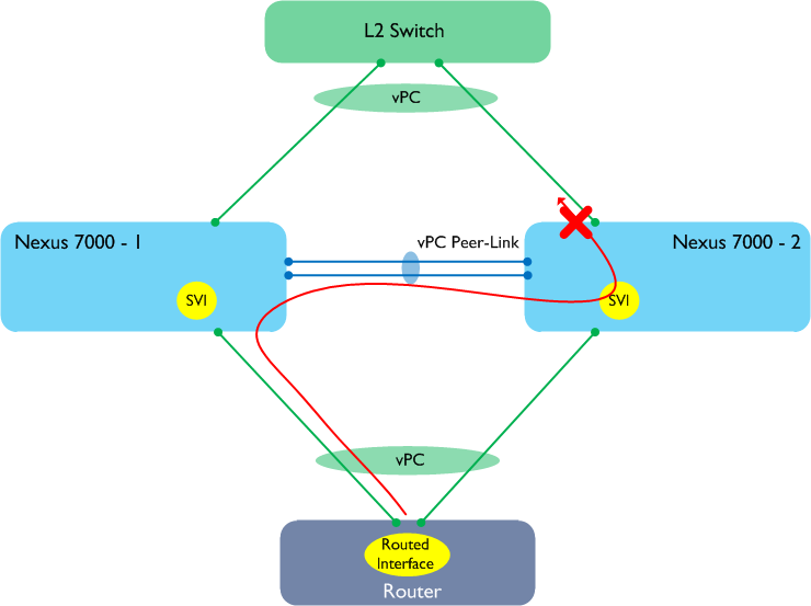
In the above example, the layer 3 next hop (from the point of view of the router at the bottom) is Nexus 7000-2, however vPC is choosing to send the frame to Nexus 7000-1. As a result, the packet passes over the Peer-Link, where it is prevented from being sent out onto another vPC member port. It is therefore probable that approximately 50% of your traffic would be lost in this scenario. So if we now enable the Peer-Gateway feature, does that help?
Peer-Gateway was introduced to get around a specific problem found on certain NAS and load balancing platforms that have a habit of replying to traffic using the MAC address of the sending device, rather than the HSRP MAC. In non-vPC environments, that never caused an issue (in fact most people probably never even noticed it happening), but when using vPC, traffic gets lost for similar reasons as in the above example. Peer-Gateway fixes this by allowing a device to route packets originally intended for the other peer. So the question is, can’t we enable Peer-Gateway to get around the L3 over vPC the above issue? The answer is yes, for the data plane. Unfortunately, the same feature has completely the wrong effect on the control plane for dynamic routing.
Issue #2: Control Plane
Let’s now add a routing protocol - OSPF - to our example. We enable OSPF on both Nexus 7000 SVIs as well as the router at the bottom of our diagram with the intention of having adjacencies between all three. Peer-Gateway is enabled to get around the data plane issue described above.
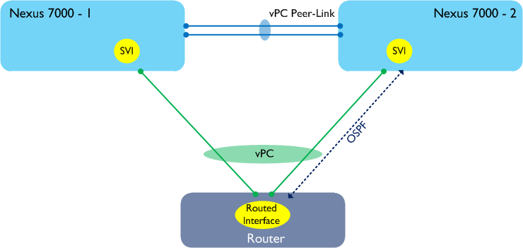
In the above diagram, I am showing one OSPF adjacency between our router and Nexus 7000-2. In reality, there are two more adjacencies (one between the router and Nexus 7000-1, and one between the two Nexus 7Ks) but I’m not showing them here for clarity. In order to form those adjacencies, let’s say that the OSPF packets between our router and Nexus 7000-2 take the alternate layer 2 path through Nexus 7000-1 as shown in the following diagram.
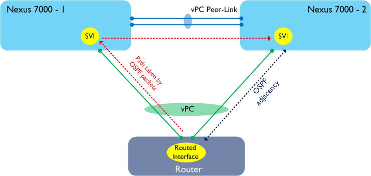
Now the important thing to remember is that we have Peer-Gateway enabled in the above topology. Peer-Gateway works by forcing routing to take place locally, which means that any OSPF packets which pass through Nexus 7000-1 are routed. What that also means is that the TTL will be decremented, and as most routing protocols use packets with a TTL of 1, the TTL is decremented to 0 - so the packet is dropped. The result of all this is that the OSPF adjacencies, in many cases, will never come up. Of course, you might be lucky and see all your packets being hashed to the ‘correct’ peer, however this is fairly unlikely.
So the bottom line is that enabling Peer-Gateway will solve one problem only to introduce another - the net result is that we cannot use this feature to support dynamic routing over vPC.
23 Mar 2013
NX-OS release 5.2(1)N1(2) added support for storm control on Nexus 2000 NIFs / FEX Fabric Interfaces (this is also available on 6.0(2)N2(1) for the Nexus 6000) - these are the interfaces used to connect the parent Nexus 5500 or 6000 to the Fabric Extender. I looked into this feature recently for a customer so thought a quick overview might be useful as there are a couple of things to be aware of.
Firstly, the storm control percentage value that you configure gets implemented as a percentage of the total speed of the port-channel between 5K / 6K and FEX. Here’s an example:
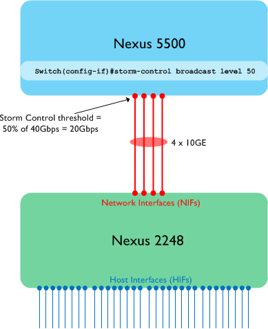
In the above drawing, we have four 10GE interfaces used as FEX Fabric ports (i.e. the links between the 5K and 2K). All four links within this port-channel on the 5K are on the same port ASIC (this matters!!), and broadcast storm control is configured on the FEX Fabric port-channel, with a value of 50%. So in this case, a total of 20Gbps of broadcast traffic would be allowed into the parent Nexus 5500 before the threshold is reached and we start dropping traffic. This is pretty straightforward and what you would expect to see.
I said in the example above that the port ASIC allocations matter - this is because the behaviour is slightly different if the FEX Fabric port-channel is spread across multiple port ASICs on the Nexus 5K. Here’s another example:
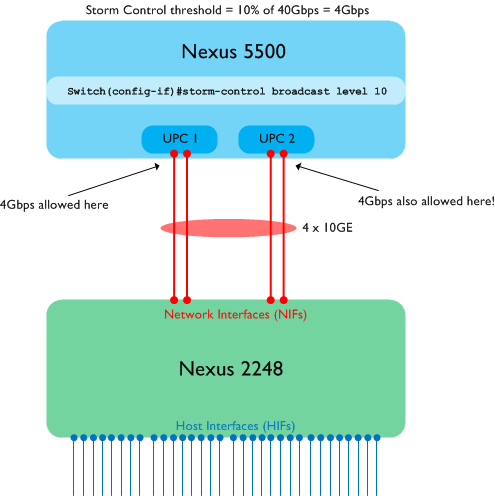
In the second example, two of the member links in the FEX Fabric port-channel are connected to ports serviced by the first UPC (Unified Port Controller) ASIC. The other two ports in the channel are using a different UPC ASIC. The storm control percentage is still calculated based on the total bandwidth in the port-channel (10%, or 4Gbps in this case) - however, importantly, each UPC port ASIC_ enforces the threshold independently_. What that means in practice is that each UPC will allow 4Gbps of broadcast traffic, for a total of 8Gbps into the switch. If you aren’t aware of this then you could end up with more traffic than you expect before the switch takes action.
Note that the above behaviour is applicable to normal port-channels as well (not just FEX NIF ports).
12 Mar 2013
The requirement for layer 2 interconnect between data centre sites is very common these days. The pros and cons of doing L2 DCI have been discussed many times in other blogs / forums so I won’t revisit that here, however there are a number of technology options for achieving this, including EoMPLS, VPLS, back-to-back vPC and OTV. All of these technologies have their advantages and disadvantages, so the decision often comes down to factors such as scalability, skillset and platform choice.
Now that FabricPath is becoming more widely deployed, it is also starting to be considered by some as a potential L2 DCI technology. In theory, this looks like a good bet - easy configuration, no Spanning-Tree extended between sites, should be a no brainer, right? Of course, things are never that simple - let’s look at some things you need to consider if looking at FabricPath as a DCI solution.
**1: FabricPath requires direct point-to-point WAN links. **
A technology such as OTV uses mac-in-IP tunnelling to transport layer 2 frames between sites, so you simply need to ensure that end-to-end IP connectivity is available. As a result, OTV is very flexible and can run over practically any network as long as it is IP enabled. FabricPath on the other hand requires a direct layer 1 link between the sites (e.g. dark fibre), so it is somewhat less flexible. Bear in mind that you also lose some of the features associated with an IP network - for example, there is currently no support for BFD over FabricPath.
**2: Your multi-destination traffic will be ‘hairpinned’ between sites.
**
In order to forward broadcast, unknown unicast and multicast traffic through a FabricPath network, a multi-destination tree is built. This tree generally needs to ‘touch’ each and every FP node so that multi-destination traffic is correctly forwarded. Each multi-destination tree in a FabricPath network must elect a root switch (this is controllable through root priorities, and it’s good practice to use this), and all multi-destination traffic must flow through this root. How does this affect things in a DCI environment? The main thing to remember is that there will generally be a single multi-destination tree spanning both sites, and that the root for that tree will exist on one site or the other. The following diagram shows an example.
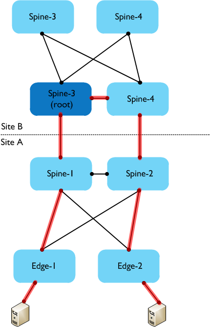
In the above example, there are two sites, each with two spine switches and two edge switches. The root for the multi-destination tree is on Spine-3 in Site B. For the hosts connected to the two edge switches in site A, broadcast traffic could follow the path from Edge-1 up to Spine-1, then over to Spine-3 in Site B, then to Spine-4, and then back down to the Spine-2 and Edge-2 switches in Site A before reaching the other host. Obviously there could be slightly different paths depending on topology, e.g. if the Spine switches are not directly interconnected. In future releases of NX-OS, the ability to create multiple FabricPath topologies will alleviate this issue to a certain extent, in that groups of ‘local’ VLANs can be constrained to a particular site, while allowing ‘cross-site’ VLANs across the DCI link.
3: First Hop Routing localisation support is limited with FabricPath.
When stretching L2 between sites, it’s sometimes desirable to implement ‘FHRP localisation’ - this usually involves blocking HSRP using port ACLs or similar, so that hosts at each site use their local gateways rather than traversing the DCI link and being routed at the other site. The final point to be aware of is that when using FabricPath for layer 2 DCI, achieving FHRP localisation is slightly more difficult. On the Nexus 5500, FHRP localisation is supported using ‘mismatched’ HSRP passwords at each site (you can’t use port ACLs for this purpose on the 5K). However, if you have any other FabricPath switches in your domain which aren’t acting as a L3 gateway (e.g. at a third site), then that won’t work and is not supported.
This is because FabricPath will send HSRP packets from the virtual MAC address at each site with the local switch ID as a source. Other FabricPath switches in the domain will see the same vMAC from two source switch IDs and will toggle between them, making the solution unusable. Also, bear in mind that FHRP localisation with FabricPath isn’t (at the time of writing) supported on the Nexus 7000.
The issues noted above do not mean that FabricPath cannot be used as a method for extending layer 2 between sites. In some scenarios, it can be a viable alternative to the other DCI technologies as long as you are aware of the caveats above.
Hope this is useful - thanks for reading!
08 Mar 2013
The lack of support for running layer 3 routing protocols over vPC on the Nexus 7000 is well documented - less well known however is that the Nexus 5500 platform operates in a slightly different way which does actually allow layer 3 routing over vPC for unicast traffic. Some recent testing and subsequent discussions with one of my colleagues on this topic reminded me that there is still (somewhat understandably) a degree of confusion around this.
Let’s start with a reminder of what doesn’t work on the Nexus 7000:
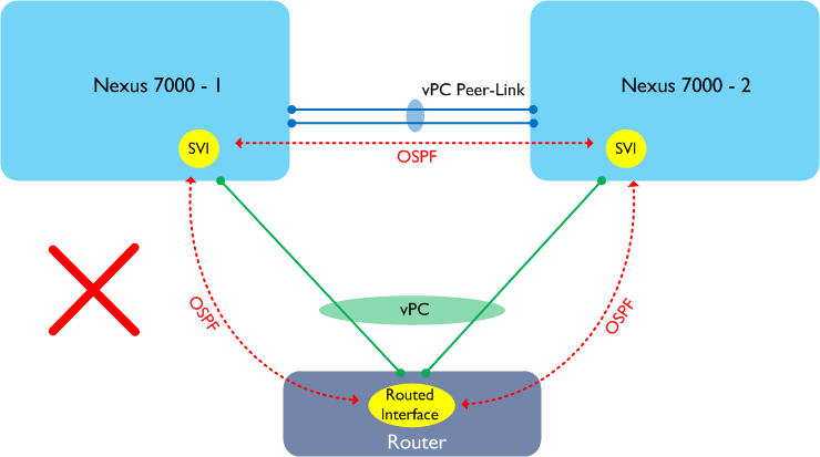
In the diagram above, a router or similar device is connected to the two Nexus 7000 switches using a vPC and is attempting to form adjacencies with each peer. This design does not work on the Nexus 7000 as traffic may need to traverse the Peer-Link in order to reach its ultimate destination. The Nexus 7000 has a rule which says “any traffic received from the Peer-Link cannot be forwarded out via another vPC”, therefore such traffic would be dropped. Here’s a slightly different example:
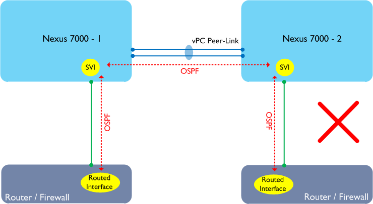
In the above example, the routers or firewalls are single attached to the Nexus 7000 switches but do not connect using a vPC. This design doesn’t work either on the Nexus 7000 as each router / firewall will form an adjacency with both Nexus 7000s, and traffic may still traverse the Peer-Link. The common solution to the above problem is to run a separate link between the two Nexus 7000s to handle the non-vPC traffic:
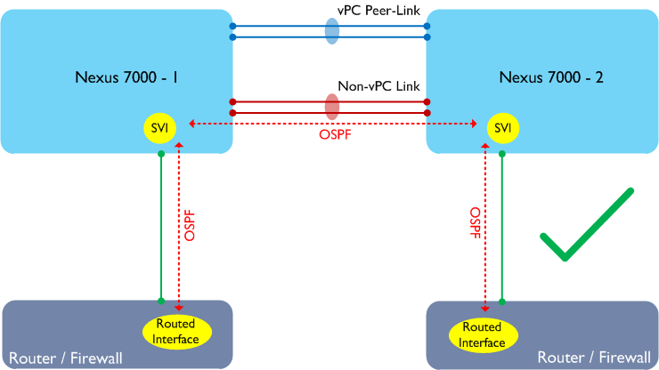
No surprises so far - the above restrictions are well documented in various guides on cisco.com.
What may surprise you is that the Nexus 5500 works in a slightly different way - as a result, there are some topologies that don’t work on the Nexus 7000 but which do work on the Nexus 5500 (when running a layer 3 module). Let’s go back to our first example above, but this time let’s replace the Nexus 7000s with Nexus 5500s running with layer 3 modules:
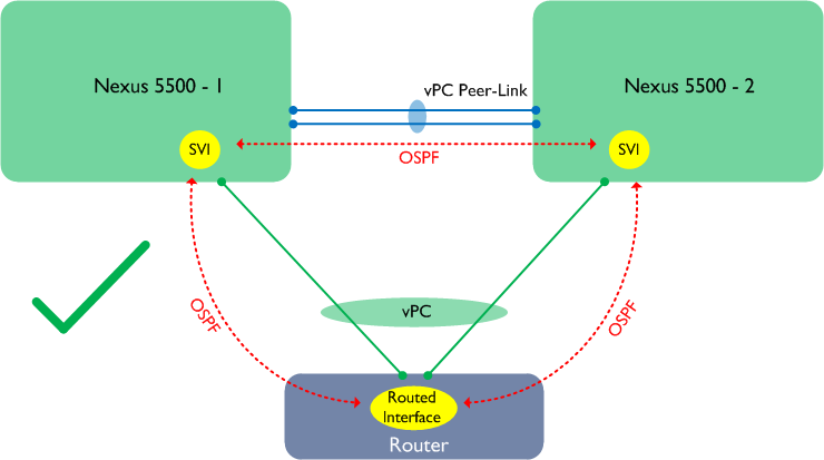
The above design is supported and works for unicast traffic__ only. Why is this? The reason is that the Nexus 5500 does not handle traffic received from the Peer-Link in the same way as the Nexus 7000, therefore this traffic will be forwarded out on another vPC. Note however that traffic flows may still be suboptimal (i.e. traffic may arrive at Nexus 5500-1, only to have to traverse the Peer-Link to reach Nexus 5500-2), however the Peer-Gateway feature can be enabled to resolve this. I should note at this point that officially, the above design still isn’t recommended (although it works and is supported) - one of the reasons for this is that multicast traffic is subject to the same restrictions as on the Nexus 7000 and therefore does not work properly in this scenario.
If this hasn’t completely blown your mind, then I have one final topology to show you:
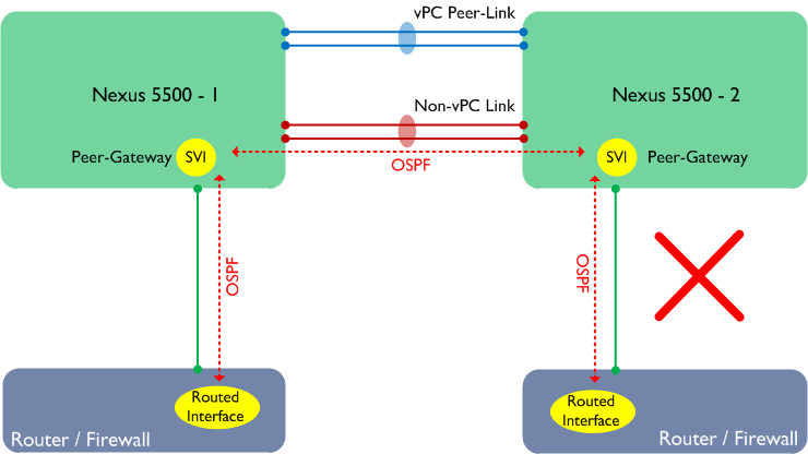
In the above example, two routers are single attached to the Nexus 5500s. There is a separate link for non-vPC traffic and the Peer-Gateway feature is enabled. This should work, right? Actually it doesn’t - in this scenario, OSPF adjacencies would not form properly. Note that this is specific to the scenario where there is a non-vPC link and Peer-Gateway is turned on. The solution to this is to revert to running the routed VLAN over the Peer-Link - which does work (for unicast traffic only).
Hopefully this will help to clear up some of the confusion - thanks for reading!


