04 Mar 2013
Virtual Port Channel (vPC) is a technology that has been around for a few years on the Nexus range of platforms. With the introduction of FabricPath, an enhanced version of vPC, known as vPC+ was released. At first glance, the two technologies look very similar, however there are a couple of differences between them which allows vPC+ to operate in a FabricPath environment. So for those of us deploying FabricPath, why can’t we just use regular vPC? Let’s look at an example. The following drawing shows a simple FabricPath topology with three switches, two of which are configured in a (standard) vPC pair. 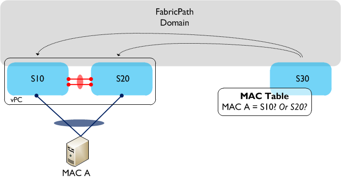 A single server (MAC A) is connected using vPC to S10 and S20, so as a result traffic sourced from MAC A can potentially take either link in the vPC towards S10 or S20. If we now look at S30’s MAC address table, which switch is MAC A accessible behind? The MAC table only allows for a one to one mapping between MAC address and switch ID, so which one is chosen? Is it S10 or S20? The answer is that it could be either, and it is even possible that MAC A could ‘flip flop’ between the two switch IDs. So, clearly we have an issue with using regular vPC to dual attach hosts or switches to a FabricPath domain. How do we resolve this? We use vPC+ instead. vPC+ solves the issue above by introducing an additional element - the ‘virtual switch’. The virtual switch sits ‘behind’ the vPC+ peers and is essentially used to represent the vPC+ domain to the rest of the FabricPath environment. The virtual switch has its own FabricPath switch ID and looks, for all intents and purposes, like a normal FabricPath edge device to the rest of the infrastructure.
 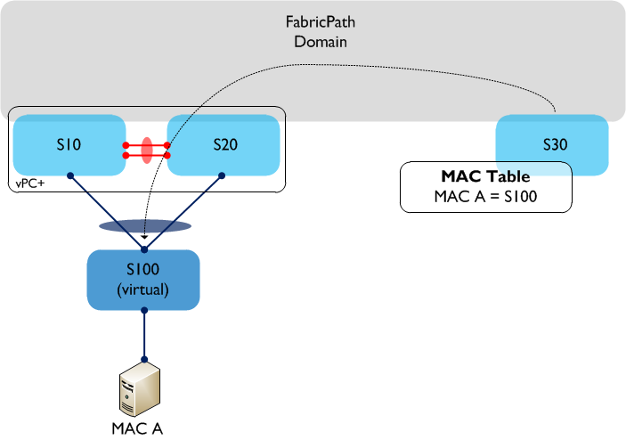 In the above example, vPC+ is now running between S10 and S20, and a virtual switch - S100 - now exists behind the physical switches. When MAC A sends traffic through the FabricPath domain, the encapsulated FP frames will have a source switch ID of the virtual switch, S100. From S30’s (and other remote switches) point of view, MAC A is now accessible behind a single switch - S100. This enables multi-pathing in both directions between the Classical Ethernet and FabricPath domains. Note that the virtual switch needs a FabricPath switch ID assigned to it (just like a physical switch does), so you need to take this into account when you are planning your switch ID allocations throughout the network. For example, each access ‘Pod’ would now contain three switch IDs rather than two - in a large environment this could make a difference. Much of the terminology is common to both vPC and vPC+, such as Peer-Link, Peer-Keepalive, etc and is also configured in a very similar way. The major differences are:
-
In vPC+, the Peer-Link is now configured as a FabricPath core port (i.e. switchport mode fabricpath)
-
A FabricPath switch ID is configured under the vPC+ domain configuration (_fabricpath switch id _) - remember to configure the same Switch ID on both peers!
-
Both the vPC+ Peer-Link and member ports must reside on F series linecards.
vPC+ also provides the same active / active HSRP forwarding functionality found in regular vPC - this means that (depending on where your default gateway functionality resides) either peer can be used to forward traffic into your L3 domain. If your L3 gateway functionality resides at the FabricSpine layer, vPC+ can also be used there to provide the same active / active functionality.
27 Feb 2013
When the Nexus 1000V was first released, the only available control mode between VSM (Virtual Supervisor Module) and VEM (Virtual Ethernet Module) was layer 2 mode. This meant that the VSM and VEM had to be layer 2 adjacent (i.e. on the same VLAN). Layer 3 control mode was released a while ago however, which meant that the VSM and VEM could be on different VLANs / subnets. L3 control also makes things slightly simpler to set up as you don’t need to worry about trunking control / packet VLANs everywhere and setting up port groups for these.
Assuming you want to use L3 control mode, there are a couple of decisions to make:
-
Which L3 interface you want to use on the VSM (control0 or mgmt0).
-
Whether you use the mgmt VMK interface or set up a dedicated VMK interface for L3 control.
Let’s look at the VSM end first. You have two choices: you can either use a dedicated control interface (control0), or you can use the existing mgmt0 interface (which gets set up when the N1KV is first installed and is also used for Telnet / SSH into the VSM). Either is fine - personally I have a slight preference to use a separate control0 interface and keep mgmt0 dedicated to management. You configure either control0 or mgmt0 under the ‘svs-domain’ config, as follows:
svs-domain
 no control vlan
 no packet vlan
 svs mode L3 interface <strong>mgmt0 | control0</strong>
Note that you need to remove the control and packet VLAN configuration as they aren’t relevant in L3 control mode.
The second choice you need to make is whether to use the existing management VMK interface, or whether a new one should be created for the VEM to VSM connectivity. As a refresher, a VMK interface is a virtual interface that the ESXi host itself uses to communicate with the outside world. Because we are trying to configure a layer 3 connection between the VSM and VEM, and because the Nexus 1000V is a layer 2 switch (therefore doesn’t have any native L3 support built in), we need a VMK interface on the ESXi host to do this.
If you choose to use the management VMK interface (normally VMK0) for layer 3 control, that VMK will need to be moved over to the Nexus 1000V, where it will sit ‘behind’ the VEM, as follows:
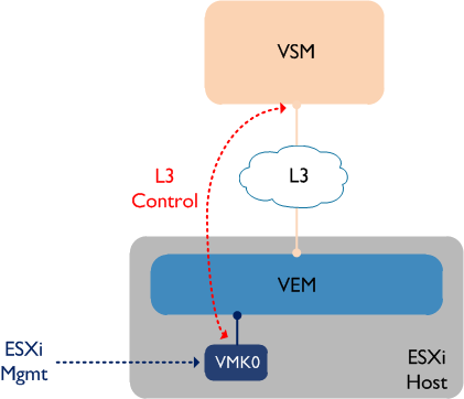
Bear in mind that the VSM will not ‘see’ the VEM (i.e. it won’t appear in the output of ‘sh mod’) until the VMK interface is moved to the VEM. This is definitely the simpler of the two options and it cuts down on some extra admin as you don’t have create a second VMK interface. However some people prefer having their ESXi management VMK interface ‘out of band’ - in other words, they prefer to have the management VMK interface remain on a standard vSwitch. This leads us to our second option:
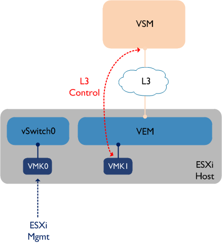
This option keeps VMK0 (ESXi mgmt) on the standard vSwitch0, while a new VMK interface (VMK1) is created and used for L3 control between the VSM and VEM. If you choose this option, you may need to configure static routes on the ESXi host if the two VMK interfaces are in different VLANs - for example, a default gateway would be configured via VMK0, while a more specific static route would be configured via VMK1 towards the VSM IP address.
25 Feb 2013
In a FabricPath deployment, it is important to have all FabricPath VLANs configured on every switch participating in the FP domain. Why is this? The answer lies in the way multi-destination trees are built.
A multi-destination tree is used to forward broadcast, unknown unicast and multicast traffic through the FabricPath network:

In the above example, S1 is the root of this multi-destination tree, with the branches of the tree shown in red. Any multi-destination traffic (such as ARP requests) from say, S10 to S20 would take the path to S1 and then back down. So what does this have to do with configuring VLANs on every switch? Let’s look at an example:
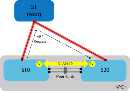
In the above example, S10 and S20 are now configured to run vPC+ - this is commonly used between switch pairs to facilitate downstream switch connectivity into the FabricPath domain. We also have a VLAN (10) spanned between S10 and S20 for backup routing purposes (also common), with SVIs on both switches. However when we try and ping from S10 to S20 on VLAN 10, it fails. Why? The multi-destination tree in this case takes the path up to S1 and back down again - the Peer-Link between S10 and S20 is not part of this tree. What this means is that ARP requests will take the longer path up to S1 and back to S20 - **however VLAN 10 is not configured on S1 **so the ARP traffic is black holed. Adding VLAN 10 to S1 resolves the issue and traffic flows normally. Note that unicast traffic will take the direct path between S10 and S20 - it is only multi-destination traffic which uses the tree.
So the moral of this story is to configure your VLANs everywhere, even if you think traffic for a given VLAN might never use a particular switch - trying to prune manually by removing VLANs from certain switches will inevitably lead to your multi-destination tree breaking and traffic being black holed.
24 Feb 2013
It’s often a good recommendation to use multiple linecard modules in a switch chassis - this makes it possible to spread port-channels across linecards so if one fails, convergence times are kept to a minimum. If you are using vPC on the Nexus 7000, this recommendation becomes even more important. Why? Let’s imagine we have a vPC setup with two Nexus 7000s and a downstream switch, connected via vPC. Each Nexus 7000 has a single M1 10GE linecard (used for both the peer-link and the upstream connections to the core), plus a single M1 1GE linecard (used to connect to the downstream switch, plus the Peer-Keepalive link):
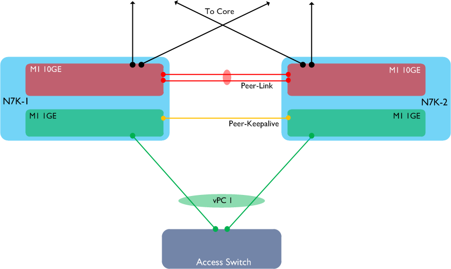
Let’s also assume N7K-1 is the primary vPC peer. Now let’s see what happens if we lose one of the M1 10GE modules in N7K-1:
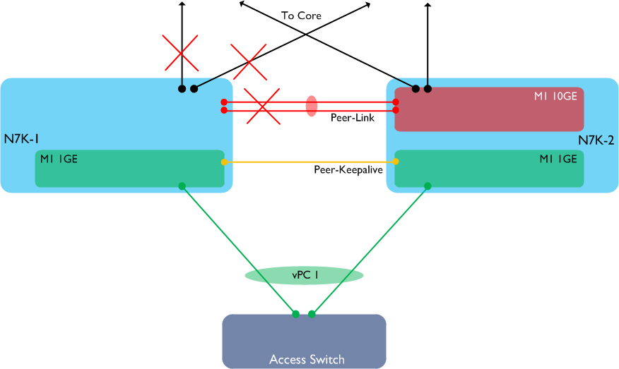
What has happened here? Because the only available 10GE linecard in N7K-1 has failed, we have lost both the vPC Peer-Link and all our uplinks to the core from this switch. However, the M1 1GE card is still available, which means that both the vPC Peer-Keepalive and the vPC member port to the access switch are still up. Anyone familiar with vPC will at this point know that if the Peer-Link is down, but the Peer-Keepalive is still available, **the secondary vPC peer will disable its own vPC member links, **as follows:
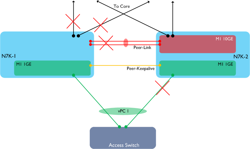
Hopefully the issue with this is clear to see: the access switch has only one available path - via N7K-1. However N7K-1 has no available links to anywhere else in the network, therefore our access switch is now completely isolated.
How do we avoid this situation? There are two solutions:
-
Purchase an additional 10GE module for each Nexus 7000
-
Deploy vPC object tracking
Option 1 is ideal, however assuming that isn’t feasible due to cost, we need to use vPC object tracking to get around this problem.
What is vPC Object Tracking, and how does it help?
Essentially, vPC Object Tracking is a method of signalling that a switch has lost a linecard and that the other vPC peer should assume the primary role (thereby keeping all its own vPC member links up). It does this using track lists, as follows:
! Track the Peer-Link
track 1 interface port-channel1 line-protocol_
! Track core uplinks_
track 2 interface Ethernet1/1 line-protocol
track 3 interface Ethernet1/2 line-protocol
!
track 10 list boolean or
object 1
object 2
object 3
!
vpc domain 1
track 10
In our example, if the above config is on N7K-1 and the 10GE module fails, N7K-1 effectively says “Hey, N7K-2, I’ve lost my Peer-Link and core uplinks. This means I must have lost my only 10GE linecard - I need you to take over the vPC primary role”. N7K-2 then assumes the primary role, which means that it will not bring down its own vPC member links. This means that traffic continues to flow from the access switch to second Nexus 7000 - problem solved!
22 Feb 2013
What is the ASA 1000V? It is a virtualised edge firewall that runs in conjunction with the Nexus 1000V switch. The ASA 1000V runs as a virtual machine, and provides a secure default gateway for other VMs in the environment. Many of the features from the physical ASAs are supported, such as NAT, failover and site-to-site IPSec VPNs, however there are a few features which are not supported in the current release such as IPv6, multiple contexts, dynamic routing and transparent mode firewalling.
An ASA 1000V has four “physical” interfaces - ‘Inside’, ‘Outside’, ‘Management’ and ‘Failover’:
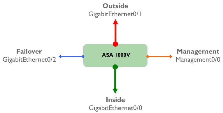
Of course, these aren’t really physical interfaces; they are virtual interfaces residing on a VM, and each of these interfaces maps directly to a port-profile that needs to be configured on the Nexus 1000V before the ASA is installed. To refresh your memory, a port profile is a collection of interface level commands on the Nexus 1000V which can be applied to one or more virtual Ethernet interfaces connecting to a VM. Logically, the ASA 1000V virtual machine is sitting ‘behind’ the Nexus 1000V VEM, and the mapping of port-profiles to ASA 1000V interfaces looks like this:

An important point to remember about the ASA 1000V is that in the initial release - 8.7(1) - only two data interfaces are supported (Inside and Outside). One of these interfaces (the Inside interface) must be designated as the ‘Service’ interface - this interface sends and receives vPath tagged traffic to and from the Nexus 1000V. I will (hopefully) explore vPath in more detail in a future post, but essentially this is a mechanism which allows the Nexus 1000V to intercept traffic and redirect it to a virtual service (which in our case is the ASA 1000V).
So how does the ASA 1000V actually protect virtual machines? For this, we need to introduce the concept of a ‘security profile’. A security profile is essentially a collection of security policies - the difference here is that the security profile gets assigned to a set of protected VMs through the use of Nexus 1000V port profiles. The following diagram shows how this looks:
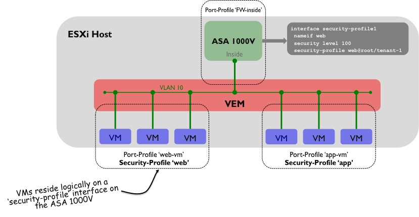
A few things are going on here:
1) A security-profile named ‘Web’ has been created on the ASA 1000V that contains the policy information to be applied to the protected VMs. This security-profile is typically created using VNMC (Virtual Network Management Centre) or through the ASDM GUI.
2) The security-profile ‘Web’ has been assigned to an interface on the ASA 1000V, named ‘security-profile1’.
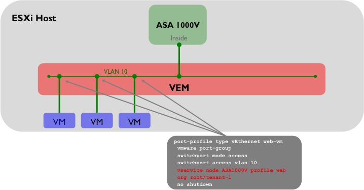
3) On the Nexus 1000V, the port-profile to which the protected VMs will be assigned (in this case named ‘web-vm’) has some additional configuration that ties the ASA 1000V security-profile to it.
4) The protected VMs use the ‘Inside’ interface of the ASA 1000V as their default gateway.
One slight area of confusion here is that although the ‘Inside’ interface of the ASA 1000V is on the same VLAN (VLAN 10 in this case) as the vNICs of the protected VMs, the Inside interface sits in a different N1KV port-profile from the protected VMs. To complete the picture, the following diagram shows how the port-profiles for the protected VMs would be configured on the Nexus 1000V:
One other point worth mentioning: traffic through the ASA 1000V can only flow between the Inside and Outside interfaces; traffic cannot flow between multiple security profiles which both sit behind the Inside interface. For that, you would need to use a VM level firewall product such as Virtual Security Gateway (VSG).
 A single server (MAC A) is connected using vPC to S10 and S20, so as a result traffic sourced from MAC A can potentially take either link in the vPC towards S10 or S20. If we now look at S30’s MAC address table, which switch is MAC A accessible behind? The MAC table only allows for a one to one mapping between MAC address and switch ID, so which one is chosen? Is it S10 or S20? The answer is that it could be either, and it is even possible that MAC A could ‘flip flop’ between the two switch IDs. So, clearly we have an issue with using regular vPC to dual attach hosts or switches to a FabricPath domain. How do we resolve this? We use vPC+ instead. vPC+ solves the issue above by introducing an additional element - the ‘virtual switch’. The virtual switch sits ‘behind’ the vPC+ peers and is essentially used to represent the vPC+ domain to the rest of the FabricPath environment. The virtual switch has its own FabricPath switch ID and looks, for all intents and purposes, like a normal FabricPath edge device to the rest of the infrastructure.
  In the above example, vPC+ is now running between S10 and S20, and a virtual switch - S100 - now exists behind the physical switches. When MAC A sends traffic through the FabricPath domain, the encapsulated FP frames will have a source switch ID of the virtual switch, S100. From S30’s (and other remote switches) point of view, MAC A is now accessible behind a single switch - S100. This enables multi-pathing in both directions between the Classical Ethernet and FabricPath domains. Note that the virtual switch needs a FabricPath switch ID assigned to it (just like a physical switch does), so you need to take this into account when you are planning your switch ID allocations throughout the network. For example, each access ‘Pod’ would now contain three switch IDs rather than two - in a large environment this could make a difference. Much of the terminology is common to both vPC and vPC+, such as Peer-Link, Peer-Keepalive, etc and is also configured in a very similar way. The major differences are:


