Learning ACI - Part 12: Inter-VRF and Inter-Tenant Communication
16 Dec 2016ACI has the ability to divide the fabric up into multiple tenants, or multiple VRFs within a tenant. If communication is required between tenants or between VRFs, one common approach is to route traffic via an external device (e.g. a firewall or router). However, ACI is also able to provide inter-tenant or inter-VRF connectivity directly, without traffic ever needing to leave the fabric. For inter-VRF or inter-tenant connectivity to happen, two fundamental requirements must be satisfied:
-
Routes must be leaked between the two VRFs or tenants that need to communicate.
-
Security rules must be in place to allow communication between the EPGs in question (as is always the case with ACI).
The question is, what is the correct way to configure this type of connectivity? I’ve seen quite a bit of confusion around this, particularly when it comes to deciding where to configure subnets (at the bridge domain level or EPG level), so hopefully I can provide a bit of clarity in this post. I’m going to cover three main scenarios:
-
Inter-VRF communication, where there is a 1:1 mapping between bridge domains and EPGs within the VRFs.
-
Inter-tenant communication, where there is a 1:1 mapping between bridge domains and EPGs.
-
Inter-VRF communication, where multiple EPGs are associated with a single bridge domain in one or both of the VRFs.
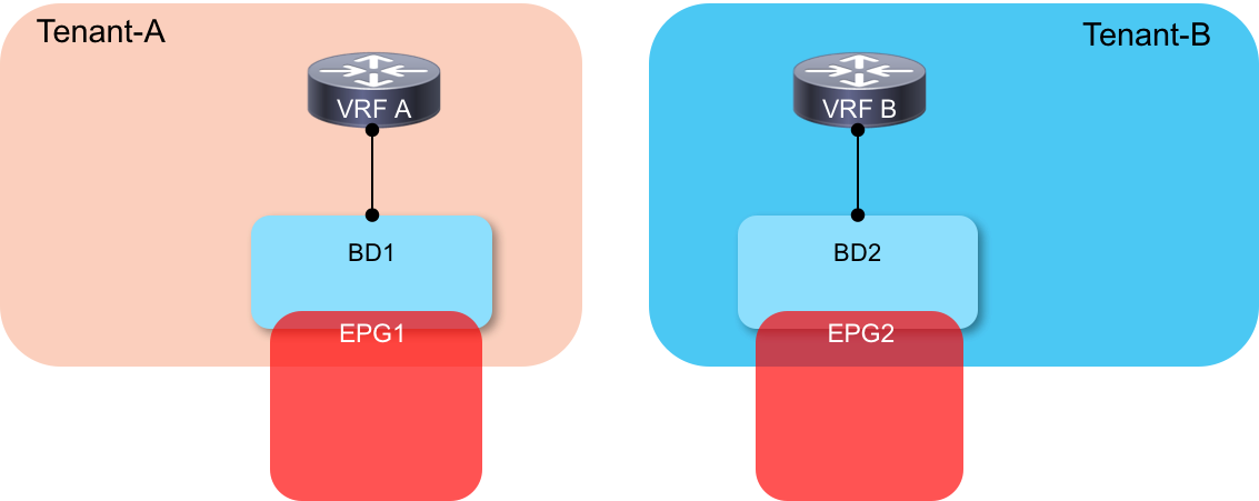
Scenario 1: Inter-VRF Communication - 1:1 Mapping Between BD and EPG
In this example, we have a simple setup with two VRFs - each VRF has a single bridge domain (BD) and End Point Group (EPG) configured as shown in the following diagram:

At the beginning of this article, I mentioned that there were two requirements when configuring inter-VRF / inter-tenant communication: leaking of routes and security rules. ACI uses contracts to control both of these.
Let’s deal first with how we leak routes from the consumer side (EPG2 in our example) to the provider side (EPG1). To make this happen, we do the following:
-
Configure our subnet at the BD level and ensure it is marked with Shared Between VRFs.
-
Create a contract that defines the appropriate port protocols we wish to allow and make sure the scope is defined as Tenant.
-
Attach the contract to the provider and consumer EPGs.
At this point, we have something like this configured:

As you can see, associating the contract with the provider and consumer EPGs within each VRF results in the consumer side BD subnet (172.16.1.0/24) being leaked to VRF A.
OK, so that’s great - we have routes leaked between VRFs in one direction (from consumer to provider). But clearly nothing is going to work until we leak routes in the opposite direction. So how do we get those routes leaked? This is the bit where a few people get tripped up.
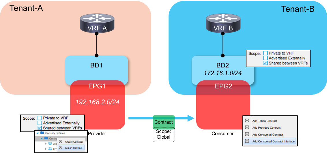
The answer is that - on the provider side - we need to configure our subnets at the EPG level, rather than the bridge domain level (as is the case in ‘normal’ deployments that don’t involve route leaking). This is shown in the following diagram:

There is a long technical explanation as to why this is necessary - I won’t bore you with that here, but fundamentally, the fabric has to be told which subnet belongs to which provider EPG, which is why the subnet must be configured at the EPG level rather than the BD level.
One point to note here is that you do not need to export contracts when configuring inter-VRF communication. This is only a requirement for inter-tenant communication.
Hopefully that’s clear so far - let’s move to our second scenario.
Scenario 2: Inter-Tenant Communication - 1:1 Mapping Between BD and EPG
In this scenario, we are going to configure communication between EPGs which sit in different tenants, as shown here:
In terms of configuration, this scenario is actually very similar to scenario 1 - we still need to configure the following:
-
Consumer subnet at the bridge domain level (marked as S_hared Between VRFs_).
-
Provider subnet at the EPG level (marked as S_hared Between VRFs_).
The major difference in this scenario is that we must now configure the scope of the contract as Global, and we must also export the contract from the provider side tenant to the consumer side tenant. On the provider side, export the contract under the Security Policies section of the tenant config. On the consumer side, we will consume the exported contract as a Contract Interface under the EPG. The final configuration looks something like this:
OK, that was easy enough - onto our last scenario where things get a little more complex.
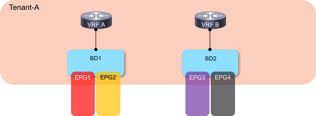
Scenario 3: Inter-VRF Communication - Multiple EPGs Associated With a Single BD
For this last scenario, we are again looking at inter-VRF communication, but this time we have more than one EPG associated with a single bridge domain in both VRFs, as shown here:
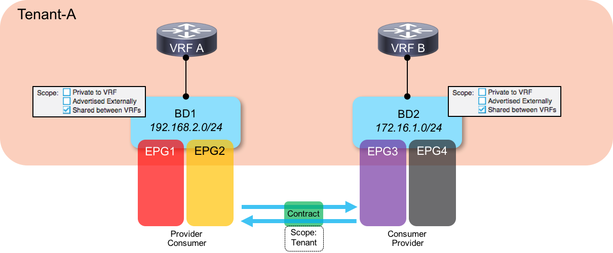
If we follow our previous examples, we would configure our consumer side subnets at the BD level and our provider side subnets at the EPG level. Hold on a minute though, there’s an issue with that - if we assume that we have only a single subnet on the provider side and that we are using that subnet for all EPGs, does that mean we have to configure the same subnet on all provider EPGs? Well actually, we can’t do that - subnets configured on an EPG must not overlap with other subnets in that same VRF. So how do we get around this?
The answer to this conundrum is that we need to return to a configuration where the subnet is configured at the BD level on both provider and consumer sides. However, one of the consequences of this is that we then need to create a bidirectional contract relationship between the EPGs - in other words, we must provide and consume the contract from both sides in order to allow route leaking to happen. This ends up looking like this:
Now, if you are familiar with ACI and the way in which rules are applied in hardware, you may spot a downside to this approach. The problem with consuming and providing a contract in both directions is that this means double the number of security rules are programmed in hardware (TCAM). If you are a heavy user of contracts in your environments, doubling up on the number of rules may be a concern for you.
If you are concerned about this doubling of rules, there is a potential solution. In order to reduce the number of rules that we need to program, we can configure the contracts that we use to be unidirectional in nature. What I mean by this is that we can un-check the boxes entitled Apply Both Directions _and _Reverse Filter Ports when we create the contract. Now, having those boxes checked is generally important for allowing return traffic back to the initiating host (on the consumer side). So if we un-check them, how do we allow return traffic?
The answer is that we configure two contracts - one that allows traffic to be initiated (let’s say it allows any port –> port 80) and one allowing the reverse traffic (let’s say port 80 –> any port). Those contracts are then applied separately to the consumer and provider side EPGs, as shown in the following two diagrams:

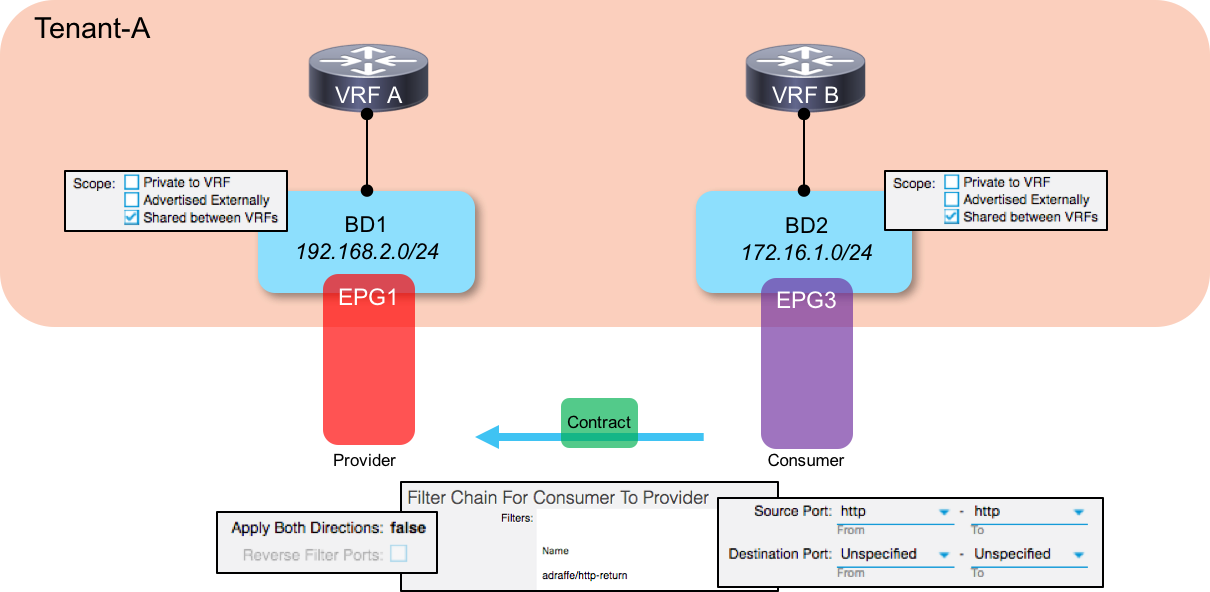
By doing this, we cut the number of entries required in the hardware required by half compared to the solution shown in the first part of this scenario.
Hopefully this helps you out a bit if you are configuring this feature - thanks for reading.