19 Jun 2015
Everything I’ve shown so far in this blog series has been focused on using the APIC GUI to achieve what we need. This is fine for small environments or for becoming familiar with ACI, but what if you need to configure 100 tenants, each with 50 EPGs, tens of private networks and bridge domains, multiple contracts to allow traffic and a L3 Outside or two thrown in? Configuring all of that through the GUI is clearly going to be massively time consuming and probably quite error prone, so we need to find a better way of doing things. ACI has a wide variety of programmability options that can be used to automate the provisioning of the fabric and its policies.
One particularly strong aspect of ACI is how easy it is for network engineers to start interacting with the fabric in a programmatic manner. Speaking from personal experience, it’s incredibly easy for someone with a ‘traditional’ network engineering background with limited development experience to start using the programmability features of ACI. With that said, let’s take a look at some of the options we have around ACI programmability:
Let’s take a look at the native REST API option first.
Native REST API
The first option - and arguably the one most people look at first - is to interact with the APIC API using raw XML or JSON. Using raw XML / JSON has the advantage of not requiring the user to have any real programming knowledge (for example, Python) and interacting with the REST API natively can be done through a variety of tools (e.g. any tool capable of posting data to a URL such as cURL, Postman plugin for Chrome, etc). So how do we get started with this?
Before you start, it’s worth bearing in mind that to use the REST API effectively, it’s useful to have some understanding of how the object model works. For example, if we want to create a tenant, private network, bridge domain and EPG using the API, we need to have a bit of knowledge about how these objects relate to each other. Fortunately, the APIC provides some tools to help us understand this - one of which is the object store browser (Visore).
To get to Visore, browse to /visore.html and log in. Once in, you'll be able to query for classes or objects using the search box at the top of the screen. In this example, I'm going to search for all instances of class _fvTenant:_
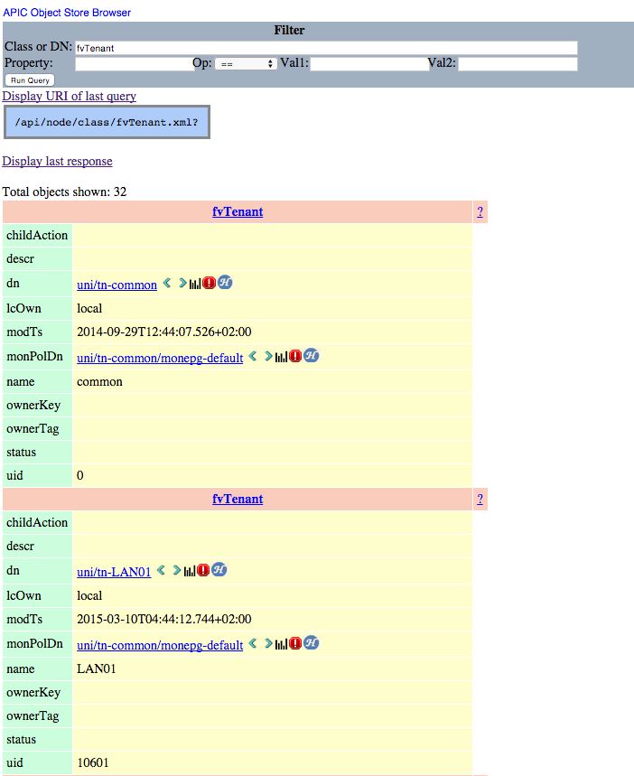
In the above screenshot, my query has returned 32 objects of class fvTenant (I have 32 tenants on my fabric), two of which I have shown here. From here, you can see the distinguished name of each tenant object (e.g. uni/tn-LAN01). Now, the really useful part of this is that clicking the right arrow (>) next to the distinguished name will take you to another screen showing all of the child objects of the tenant object in question:
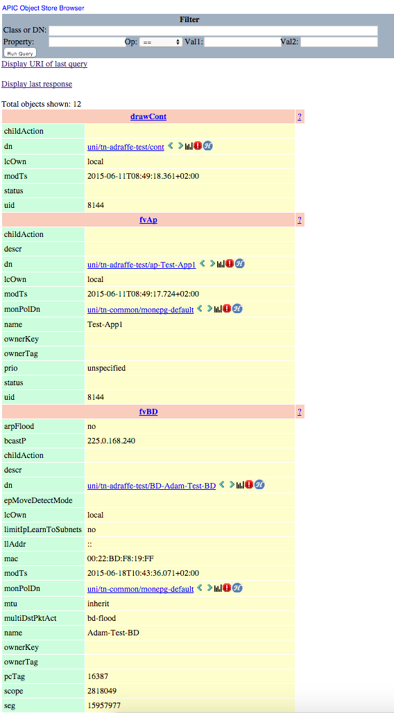
In the above screenshot, you can see two of the child objects for my tenant (named “adraffe-test”) - specifically, we see an application profile (class fvAp, named “Test-App-1”) and a bridge domain (class fvBD, named “Adam-Test-BD”). Scrolling further down reveals additional objects such as private networks, contracts and filters. Clicking the right arrow next to the DN takes you further down the tree - for example, drilling further into the “fvAp” object here would take me to the EPG objects contained within.
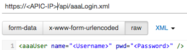
Now that we have some knowledge of the object model, we can start with some basic interaction with the REST API. The first thing I need to do is authenticate, which I can do by posting to the URL in the screen shot below and sending the XML shown:
Now that I’ve authenticated, I can start creating some objects through the ACI. I’ll start by creating a new tenant named ‘Finance’:

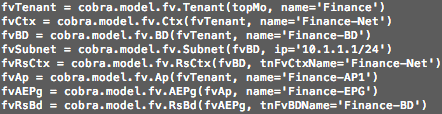
That’s it - sending that simple piece of XML to the APIC created a new tenant. Now let’s create a private network, bridge domain, application profile and EPG inside my new tenant. I post to the same URL as in the last example (the “uni” in the URL is used to represent “policy universe”), but this time I send the following:
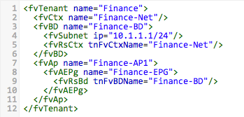
Let’s take a closer look at what the above XML does. Firstly, I need to include the parent tenant object I want to modify (Finance). I then create a new private network (fvCtx) named Finance-Net. Next, I create a bridge domain (fvBD) named Finance-BD, with a subnet address (fvSubnet) of 10.1.1.1/24. I also create a relationship between my new bridge domain and the private network I created earlier (using fvRsCtx). Next up, I create an application profile (fvAp) called Finance-AP1 and add a new EPG (fvAEPg) to it named Finance-EPG. Finally, I create a relationship from my new EPG to the BD I created earlier (using fvRsBd).
This is extremely easy to get the hang of - you can use the API inspector and “Save As” tools which I referred to in my earlier post (as well as Visore) to help you to get familiar with the object model and build your own scripts.
ACI Python SDK (Cobra)
If you are familiar with Python, Cisco have a Python SDK (also known as “Cobra”) available. This SDK allows you to build a Python program to make API calls to the APIC without having to post raw XML or JSON as in the last example. You still need a working knowledge of the object model, which again the tools mentioned above can help with.
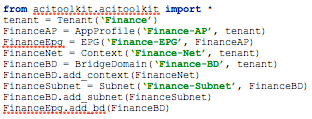
As a comparison, let’s take a look at the equivalent Python code which would create the same tenant, private network, bridge domain and EPG we created earlier (note that there is more to this script not shown here, such as importing the relevant modules, logging into the APIC, etc):
Anyone not familiar with Python may at this point be wondering if they should steer clear of the Python SDK - however, fear not: there is an extremely cool tool which will take the XML or JSON which you provide and automatically generate Python code for you. This tool is called arya (APIC REST Python Adapter) and is available here:
https://github.com/datacenter/arya
You can see this tool in action by simply downloading some XML / JSON from the APIC using the “Save As” feature and then feeding the file into the arya tool. The tool will generate the equivalent Python code for the XML or JSON you provided. Pretty cool, right?
ACI Toolkit
The final option I’ll look at here is the ACI Toolkit. One of the considerations for using either the native REST API or the Cobra SDK is that you do need to have some familiarity with the ACI object model. That’s not necessarily a huge mountain to climb, but some people may be looking for a quicker and simpler way of accessing the programmability features available with ACI. Step forward, ACI Toolkit.
The ACI Toolkit is essentially a set of Python libraries which takes the ACI object model and abstracts it into a greatly simplified version. Right now, the ACI Toolkit doesn’t provide full feature coverage in the same way that the native API or Cobra SDK does, but if you are looking for a simple way to create the most commonly used objects (EPGs, BDs, private networks and so on) then it’s worth taking a look at what the Toolkit can offer.
Here is an example of how the ACI Toolkit can be used to create some common objects within ACI:
One other nice bonus of the ACI Toolkit is that a number of applications are thrown in, such as the Snapback app (used for config rollback within ACI), End Point Tracker (used to keep track of and display end point information within the fabric), various visualisation tools and more.
You can get more info on the ACI Toolkit, including instructions to install here.
To sum up, hopefully it’s clear from this post that programmability in ACI is not limited to developers - anyone with a background in traditional networking should be able to get up to speed reasonably quickly and be able to start taking advantage of the benefits associated with programmability.
Thanks for reading.
29 Mar 2015
So far in this series, everything we have discussed has been concerned with what happens inside the ACI fabric. At some point however, you will want to connect your fabric to the outside world, either at layer 2 or layer 3. In this part, we’ll take a look at how to set up layer 3 connectivity from ACI to an external router, using a construct called the Layer 3 Outside.
Let’s first take a look at the topology I’m going to discuss in this post:
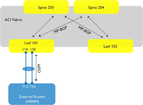 . As you can see, we are going to set up a connection from the fabric using leaf node 101 (this will be our border leaf) to an external router - in this case, a Cisco 4900M. The physical connection between the leaf node and the 4900M will be a port-channel consisting of two interfaces. We will run OSPF between the fabric and our external router. Note also from the above diagram that MP-BGP will be running inside the fabric - this is needed for the distribution of external routing information through the fabric. The existence of MP-BGP is purely for this internal route distribution within the ACI fabric - it is not running outside the fabric, e.g. there is no MP-BGP peering between the fabric and any external entity.
Enable MP-BGP Inside the Fabric
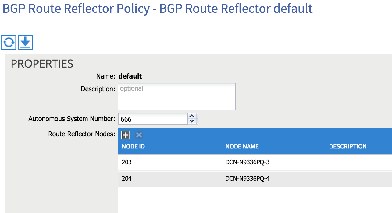
The first thing we need to do is enable MP-BGP to allow for the distribution of external routes inside the fabric. By default, BGP isn’t enabled, but enabling it is a simple matter. From the main Fabric tab, select Fabric Policies, drill down to Pod Policies and then under Policies, you’ll find an item entitled BGP Route Reflector Default. Select this item and on the right hand side of the screen, you’ll see there are two things to configure: AS number and Route Reflector Nodes.
First, choose an AS number (bear in mind that you need to match the AS number outside of your fabric if you intend to use iBGP between the fabric and external routers). You can then choose which spine nodes you want to act as route reflectors inside the fabric - in the example below I am using both of the spine nodes in my network as route reflectors (203 and 204):
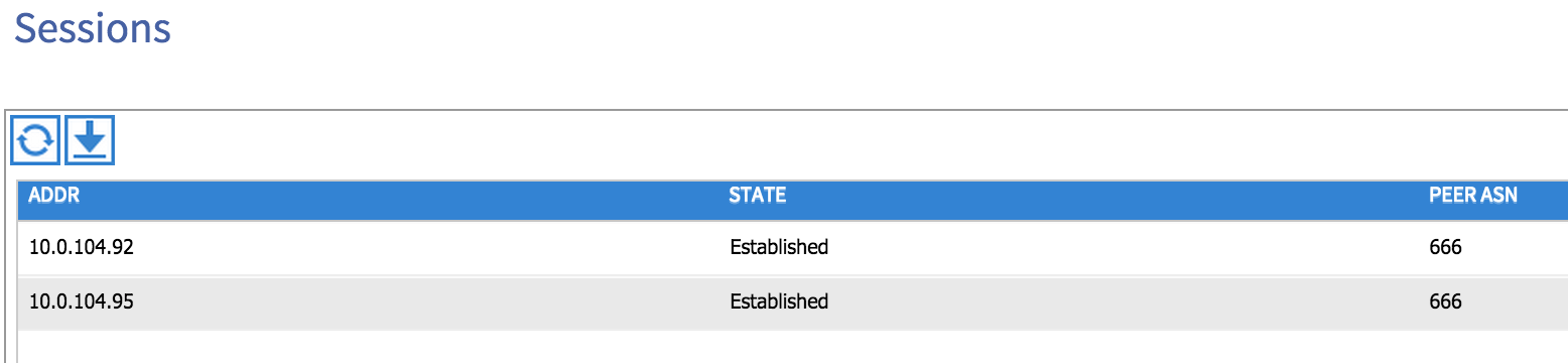
That’s all we need to do to enable BGP to run - you can check that this is the case from the Inventory tab under the Fabric menu. Select one of your spine nodes and then drill down to Protocols and then BGP - you should see some sessions formed to the lead nodes in your network:
Configure Access Policies
Now that we have MP-BGP enabled inside the fabric, the next step is to configure any access policies required. In this post, I’m going to use a VLAN and SVI combination to build the layer 3 connection between the fabric and my external router. I’ll therefore need to configure a VLAN pool, Attachable Entity Profile, Interface Policy Group, etc and apply those to the interfaces I will use for the external L3 connection.
I’ve already covered configuration of access policies in part 6 so I won’t cover that again here, but one key difference here is that rather than configuring a physical domain (as shown in part 6), I now need to use an External Routed Domain and apply my VLAN pool to that domain instead.
Configure the External Routed Network
Before we go any further, let’s take a look at what I am trying to achieve logically:
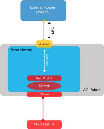
I have a single virtual machine residing in an End Point Group (EPG) named ‘Web’. This EPG is associated with a bridge domain, also named Web - the BD has a gateway of 192.168.1.1 configured which the VM can ping. I am going to create a layer 3 outside to allow OSPF routing to the 4900M external switch - finally, I am going to configure a contract between my internal ‘Web’ EPG and the external destinations I am trying to reach.
We can now switch to the tenant view and begin to configure the L3 Outside - under the Networking menu underneath the tenant, you’ll find External Routed Networks. Right click on this item and select Create Routed Outside. In the dialog box you are presented with, you’ll need to name the L3 Outside, select BGP or OSPF as the routing protocol (or neither if you want to use static routing), select the private network (context) you want to associate this L3 Outside to and select the external routed domain you configured during the access policy configuration in the last section:
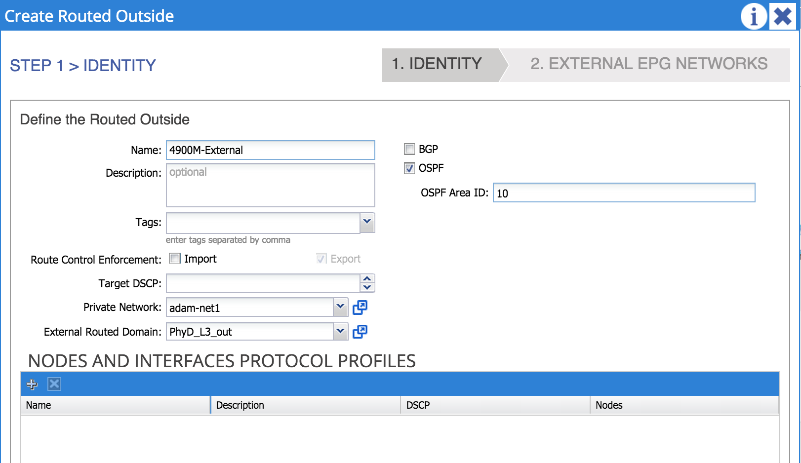
In the above example, I am naming my L3 Outside ‘4900m-External’. I have chosen OSPF as the routing protocol with area 10 and associated this L3 Outside to a private network named ‘adam-net1’. I have also associated this L3 Outside with an external routing domain named ‘PhyD_L3_out’ which I created earlier.
An important point here is that the ACI fabric (at the time of writing) supports OSPF running as an NSSA (not so stubby area) only.
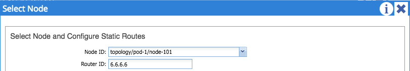
The next step is to configure nodes and interfaces. First, click the plus sign under ‘Nodes and Interfaces Protocol Profiles’, configure a name for your node profile and and then the plus sign next to ‘Nodes’. From here, you can select the leaf node that you are using for the L3 Outside (in my case I am using Node-101) and configure a router ID for the node:
After submitting, add an OSPF interface profile. From here, you can select the interface type and interfaces which you want to use for this connection. Note here that there are three types of interface available: Routed Interfaces, SVIs, or Routed Sub-Interfaces. I’m going to use the SVI option here, which means that I will have a VLAN between my fabric and external router:
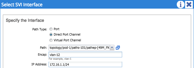
In my example, I am using a port-channel for the physical connection between my fabric and external router - I’ve selected VLAN 12 as the encapsulation (this must fall within the range configured in the VLAN pool you are using!). Finally, I’ve configured an IP address of 172.16.1.1/24 for the SVI on this border node. One important point here is that this SVI is not the same as an anycast gateway configured as part of a regular bridge domain. This is a separate SVI interface used solely for external routing from the border leaf node. Submit this configuration and go back to the main interface profile page. We now need to create an OSPF interface policy using the drop down box in the middle of the page:
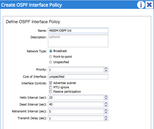
I’ve named my OSPF interface policy ‘4900M-OSPF-Int’ and selected broadcast as a network type. One important thing you must do here is tick the ‘advertise subnet’ check box - if you don’t tick this, nothing will be advertised from your L3 Outside! Once you’ve completed this, you can submit your interface profile.
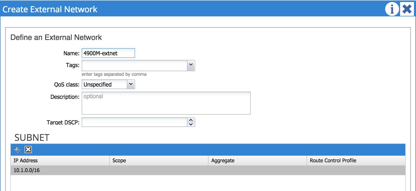
That’s it for the interface and node configuration - the next step is to configure external networks. An external network (sometimes referred to as an ‘external EPG’) is simply an external destination that we are trying to reach from within the fabric; in my example I’m configuring 10.1.0.0/16 as my external destination. Note that it is possible to use 0.0.0.0/0 if you want to define any address as a destination in the external network.
At this point, I am going to configure my external router with some basic OSPF config - I’ll add an SVI on the 4900M for VLAN 12, configure an IP address of 172.16.1.2/24 and add the network to OSPF.
interface Vlan12
 ip address 172.16.1.2 255.255.255.0
!
router ospf 1
 area 10 nssa
 router-id 5.5.5.5
 network 172.16.1.0 0.0.0.255 area 10
I also have a number of loopback interfaces configured as part of area 0.
Let’s now take a look at our fabric to see if any OSPF adjacencies are up. From the Fabric tab, I choose Inventory and then drill down to the leaf node in question (in my case node 101). Under Protocols and then OSPF, I can choose to view OSPF neighbours, interfaces, routes and so on. If I look at under Neighbors, I see my 4900M external router as an adjacency:
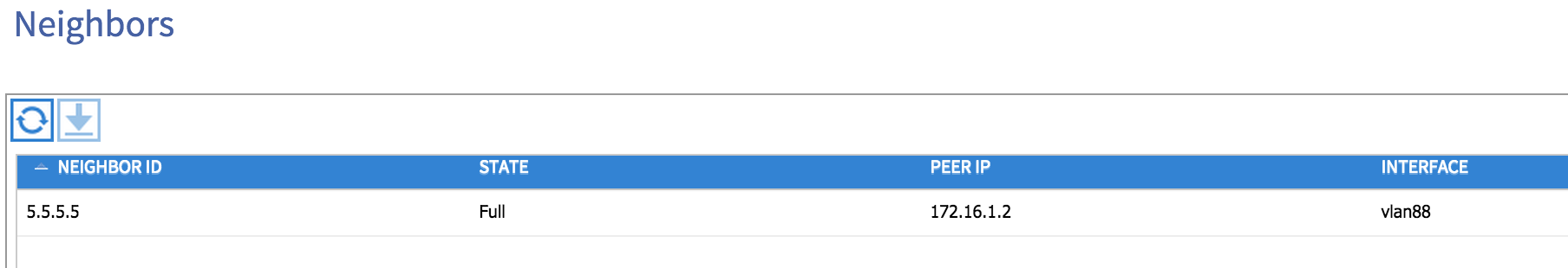
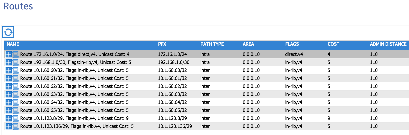
Note that VLAN 88 has been automatically chosen by the fabric as the SVI interface on the leaf node. If I now look at the ‘Routes’ option, I can see that my external router is advertising a number of prefixes to my fabric:
Let’s now check on my external router to see whether any routes have been advertised from my fabric:
DCN-4900M-2#sh ip route
Codes: L - local, C - connected, S - static, R - RIP, M - mobile, B - BGP
       D - EIGRP, EX - EIGRP external, O - OSPF, IA - OSPF inter area
       N1 - OSPF NSSA external type 1, N2 - OSPF NSSA external type 2
       E1 - OSPF external type 1, E2 - OSPF external type 2
       i - IS-IS, su - IS-IS summary, L1 - IS-IS level-1, L2 - IS-IS level-2
       ia - IS-IS inter area, * - candidate default, U - per-user static route
       o - ODR, P - periodic downloaded static route, H - NHRP, l - LISP
       + - replicated route, % - next hop override

Gateway of last resort is not set

      10.0.0.0/8 is variably subnetted, 10 subnets, 2 masks
C        10.1.60.60/32 is directly connected, Loopback60
C        10.1.60.61/32 is directly connected, Loopback61
C        10.1.60.62/32 is directly connected, Loopback62
C        10.1.60.63/32 is directly connected, Loopback63
C        10.1.60.64/32 is directly connected, Loopback64
C        10.1.60.65/32 is directly connected, Loopback65
C        10.1.123.8/29 is directly connected, Vlan31
L        10.1.123.12/32 is directly connected, Vlan31
C        10.1.123.136/29 is directly connected, Vlan41
L        10.1.123.140/32 is directly connected, Vlan41
      172.16.0.0/16 is variably subnetted, 2 subnets, 2 masks
C        172.16.1.0/24 is directly connected, Vlan12
L        172.16.1.2/32 is directly connected, Vlan12
Hmm, nothing seems to be advertised from the fabric to the 4900M - why is this? There are a couple of settings we need to configure on the bridge domain in order for subnets to be advertised. First of all, I need to flag the internal subnets I want to advertise as Public. This setting is found within the subnet configuration under the bridge domain:
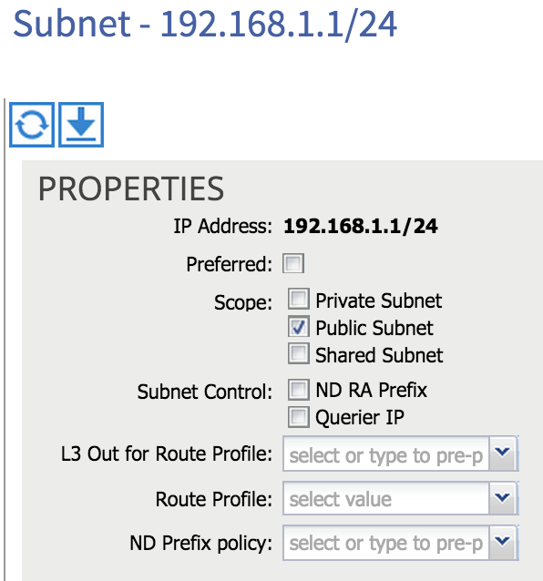
Secondly, I need to associate my bridge domain with the L3 Outside. If I click on my bridge domain, there is a box named ‘Associated L3 Outs’:
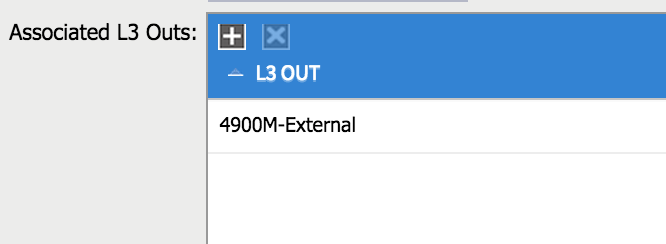
Once I have associated my L3 Outside to my bridge domain, the subnet in question (192.168.1.0/24) is advertised to my external router:
DCN-4900M-2#sh ip route
Codes: L - local, C - connected, S - static, R - RIP, M - mobile, B - BGP
       D - EIGRP, EX - EIGRP external, O - OSPF, IA - OSPF inter area
       N1 - OSPF NSSA external type 1, N2 - OSPF NSSA external type 2
       E1 - OSPF external type 1, E2 - OSPF external type 2
       i - IS-IS, su - IS-IS summary, L1 - IS-IS level-1, L2 - IS-IS level-2
       ia - IS-IS inter area, * - candidate default, U - per-user static route
       o - ODR, P - periodic downloaded static route, H - NHRP, l - LISP
       + - replicated route, % - next hop override

Gateway of last resort is not set

      10.0.0.0/8 is variably subnetted, 10 subnets, 2 masks
C        10.1.60.60/32 is directly connected, Loopback60
C        10.1.60.61/32 is directly connected, Loopback61
C        10.1.60.62/32 is directly connected, Loopback62
C        10.1.60.63/32 is directly connected, Loopback63
C        10.1.60.64/32 is directly connected, Loopback64
C        10.1.60.65/32 is directly connected, Loopback65
C        10.1.123.8/29 is directly connected, Vlan31
L        10.1.123.12/32 is directly connected, Vlan31
C        10.1.123.136/29 is directly connected, Vlan41
L        10.1.123.140/32 is directly connected, Vlan41
      172.16.0.0/16 is variably subnetted, 2 subnets, 2 masks
C        172.16.1.0/24 is directly connected, Vlan12
L        172.16.1.2/32 is directly connected, Vlan12
<strong>O N2  192.168.1.0/24 [110/20] via 172.16.1.1, 00:00:03, Vlan12</strong>
So at this point, we should be able to ping between internal and external networks, right? Actually we can’t:
DCN-4900M-2#ping ip 192.168.1.2 source loopback60
Type escape sequence to abort.
Sending 5, 100-byte ICMP Echos to 192.168.1.2, timeout is 2 seconds:
Packet sent with a source address of 10.1.60.60
.....
Success rate is 0 percent (0/5)
The reason we still have no connectivity is that I do not yet a contract in place between my internal EPG (Web) and my external network (10.1.0.0/16). I can add this by clicking on the external network (external EPG) I created during the L3 Outside configuration:
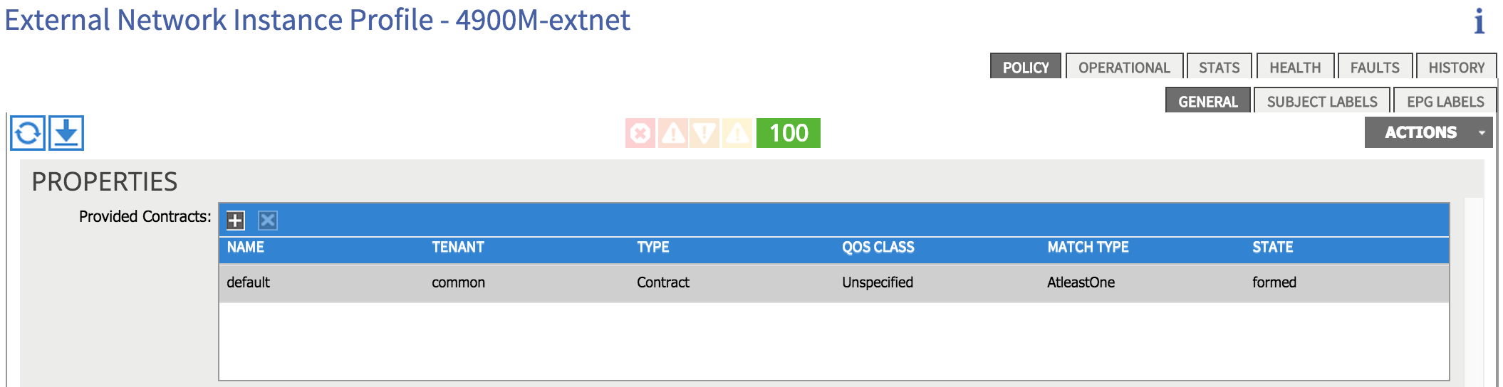
I’ve simply provided the ‘default’ contract (which permits anything) from the external network. I’ll consume the same contract from my internal ‘Web’ EPG, which results in the following:
Let’s try initiating a ping again from the external router:
DCN-4900M-2#ping ip 192.168.1.2 source loopback60
Type escape sequence to abort.
Sending 5, 100-byte ICMP Echos to 192.168.1.2, timeout is 2 seconds:
Packet sent with a source address of 10.1.60.60
!!!!!
Success rate is 100 percent (5/5), round-trip min/avg/max = 1/1/4 ms
So now that we have the contracts in place, we have full connectivity between our internal and external network.
Thanks for reading!
27 Feb 2015
Welcome to part 8 - let’s quickly recap what we have covered so far in this series:
-
Part 1 introduced this series and discussed what topics would be covered, as well as a very brief overview of ACI.
-
In part 2, I took a look at the fabric bring up process
-
Next, we took a tour through the APIC GUI to get us familiar with the interface.
-
Part 4 looked at some of the most important ACI constructs - app profiles, EPGs, contracts and filters.
-
We had a look at networking concepts in ACI in part 5.
-
In part 6, we discussed access policies and how they are used to provision ports.
-
Last time out in part 7, I walked through setting up basic connectivity between two bare metal hosts.
OK, so what’s next? In this part, we’ll discuss VMM Integration. What does this mean exactly? Firstly, VMM stands for Virtual Machine Manager - in other words, we are talking about integration with a VM management system such as VMware vCenter, Microsoft SCVMM and so on. At the time of writing this post, ACI supports integration with vCenter (others will be supported later), so this is what we’ll concentrate on here. I should also point out that we could also use the Cisco Application Virtual Switch (AVS) to achieve this integration, but I’m going to focus on using the regular VMware distributed virtual switch in this post.
But what exactly do we gain by integrating ACI with a VM management system? Why would we actually want to do this? Consider a simple example in a ‘traditional’ environment: let’s say a server virtualisation administrator is provisioning a set of virtual machines to be used for a certain application. These VMs will be used across a number of application tiers (let’s say web, app and DB just for simplicity). We can assume that there will be a port group at the virtual switch layer corresponding to each application tier and that each one will presumably map back to a VLAN on the physical network. But which VLAN should be used for each port group? The virtualisation administrator will need to work together with the network administrator to agree on which VLAN should be used for each application tier / port group. Is this really something a virtualisation admin wants to be worrying about? For that matter, does the network admin want to be worried about which VLAN is used for any given application tier? The answer in most cases is “no”, which is precisely where ACI VMM integration comes in.
So how does this work? Fundamentally, configuring VMM integration from ACI results in a connection being made between the APIC and the vCenter server, at which time an “APIC controlled” distributed virtual switch is automatically created at the vSphere level. There is nothing particularly special about this DVS - the only difference from a ‘normal’ DVS is that this one is automatically created by the APIC and controlled by ACI. To understand what this allows us to do, take a look at the following drawing:

In this example, we have created a tenant on the ACI fabric called IT. Within the IT tenant, we have an application profile named App1. Within this app profile, we are creating three End Point Groups (EPGs) corresponding to our three-tiered application (Web, App, DB). Now this is where it gets interesting - as we created our EPGs, the APIC automatically created a corresponding port group on the DVS. Note the naming of the port group as tenant|app-profile|EPG-name, for example IT|App1|Web. You might also notice that each of our port groups has been allocated a VLAN (e.g. Web = VLAN 100, App = VLAN 101, etc). These VLANs have been automatically allocated to our port groups by the APIC - they have been taken from a dynamic VLAN pool which we have pre-configured on the APIC.
What does the virtualisation administrator have to do here? He or she simply adds the VMs to the correct port groups - no need to worry about provisioning these port groups, or which VLAN should be associated with each one - it all happens automatically.
Now that we understand what VMM integration provides, how do we configure it? For this to work, there are two things that must happen: firstly, the APIC obviously needs to communicate with the vCenter; secondly, the APIC must learn the location of the ESXi host (i.e. which switch / port it is connected to) using either CDP or LLDP.
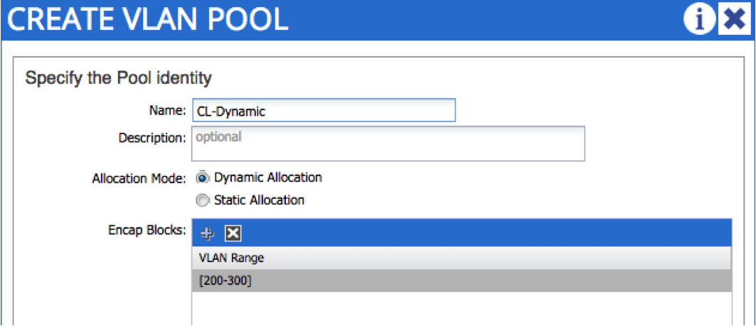
Let’s start by setting up the VMM domain. The first thing we do is create a dynamic VLAN pool. You may remember in part 6, we set up a static VLAN pool for bare metal host connectivity. In that case, VLANs were allocated manually by the administrator - in this case, we want VLANs to be allocated automatically upon EPG creation, hence the dynamic nature of the pool. In the following example, I am creating a dynamic VLAN pool named “CL-Dynamic”, with VLANs in the range 200 - 300:
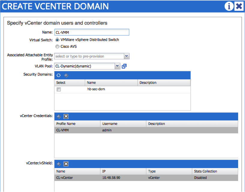
The next step is to create the VMM domain itself. To do this, you need the credentials and IP address / hostname of the vCenter - notice that you also reference the dynamic VLAN pool created in the last step:
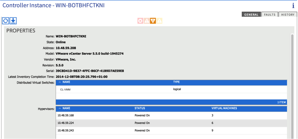
If all is well, you should now see an active connection to the vCenter (from the ‘Inventory’ tab under VM Networking). You should see details about the vCenter version as well as some info about the ESXi hosts:
One piece of manual configuration you will need to perform here is to add the physical NICs on the ESXi host (vmnics) to the new DVS that was just created.
At this point, you need to create an attachable entity profile and interface policy - the AEP should reference the VMM domain we just created. When creating the interface policy, be sure to enable CDP or LLDP as this is needed to discover the location of the ESXi host. Finally, associate the interface policy to the relevant switches and ports. Refer back to part 6 for more guidance on this process.
If you have configured everything correctly, checking the relevant vmnic under the ESXi hosts in the VM Networking Inventory tab in the APIC should display the leaf port to which the host is connected:
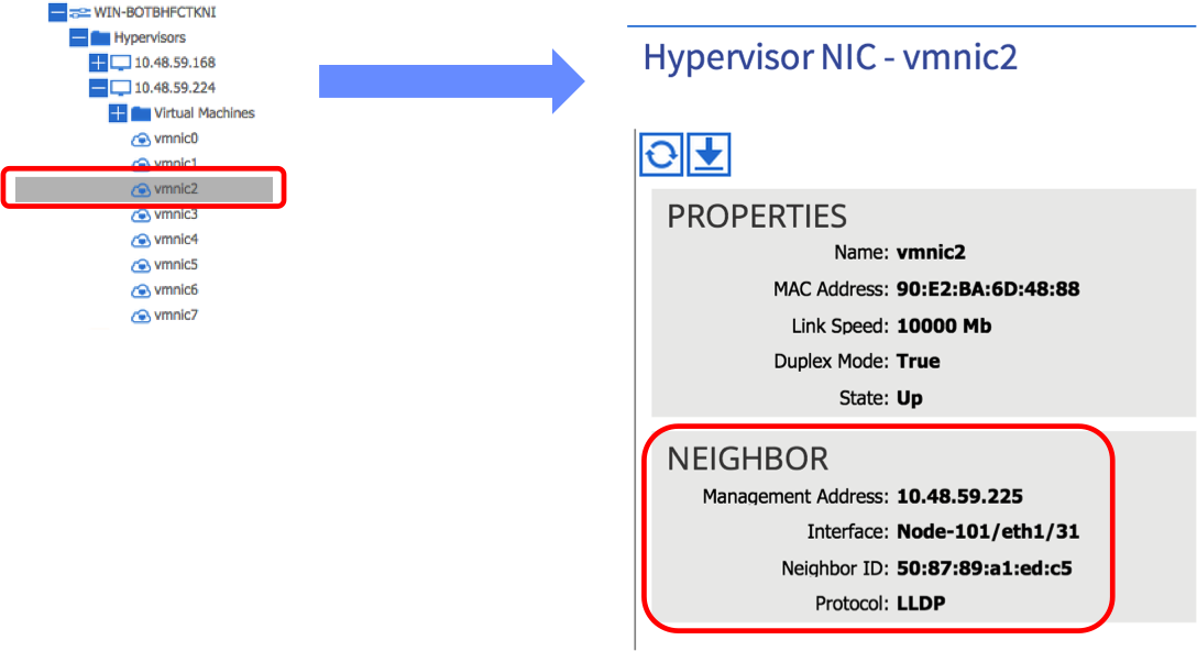
In the above example, we can see that vmnic2 on this particular ESXi host is learning that it is connected to leaf node 101 on port 1/31 via LLDP. Note that this step is important - if you don’t see the LLDP / CDP information under the correct vmnic, the APIC will not know which ports to apply policy to and connectivity will ultimately fail.
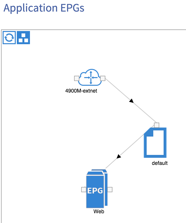
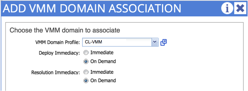
The final step is to actually to create the EPG - recall in part 7, we associated our EPG with a physical domain - we follow a similar process here, but this time we are associating our EPG with the _virtual domain _we just created:
Once we have done this, we should see the port group that corresponds to our EPG appear on the DVS:

Here, you can see that I have an EPG named ‘CiscoLiveEPG’ as part of an application profile called ‘CiscoLiveApp’, all contained under a tenant named ‘adraffe’. The APIC has created a port group with the corresponding name and has used a VLAN from the dynamic pool that we created originally.
All that remains now is for the virtualisation administrator to attach the VM to this port group and you are done!
Hopefully this has given you a good overview on VMM integration - this is a cool feature which can really reduce the burden on both network and server admins. Thanks for reading.
18 Feb 2015
Welcome back! In this instalment, I’ll look at how to get two bare metal hosts talking to each other in the fabric. In the last post, we talked about access policies. At the end of that post, we had created a number of policies and applied them to our switching nodes. If you recall, by doing that we had provisioned a range of VLANs on one or more ports on a leaf node, but we had not actually enabled any VLANs on a port. In order to do that, we need to create at least one EPG and associate it with a port.
Here is the simple topology I’m going to use in this post:
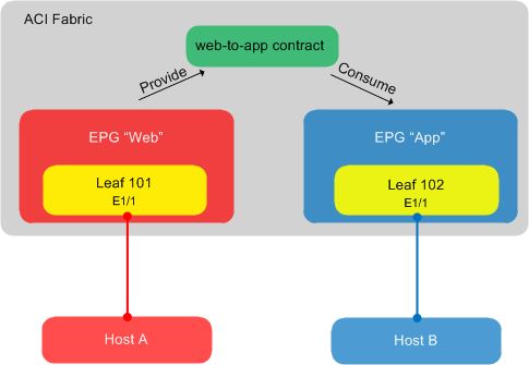
In the above diagram, we have two hosts – host A and host B. Host A is connected to port E1/1 on leaf node 101, while host B is connected to port E1/1 on leaf node 102. We are going to place host A into the ‘Web’ EPG, with host B being placed into the ‘App’ EPG. Because these are bare metal hosts, the association of ports to EPGs will be done statically.
When we configured our access policies in part 6, we provisioned a pool of VLANs (500-550) on the ports that we wished to use on our leaf nodes. We are going to pick two VLANs from this pool – one for each of our bare metal connections – and use those VLANs as part of the static EPG mapping.
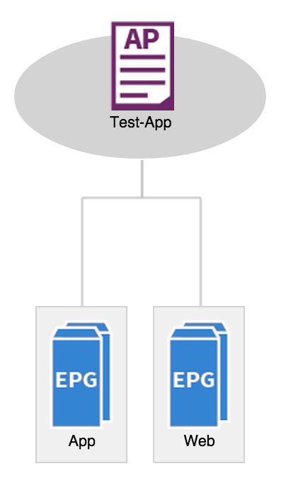
I’m making an assumption here that you already have a tenant, private network, bridge domain and subnet configured (as described in part 5). Assuming that has been done, let’s go ahead and create an application profile. Remember, an application profile is simply a container for EPGs and any associated contracts – app profiles are found under the ‘tenant’ tab:
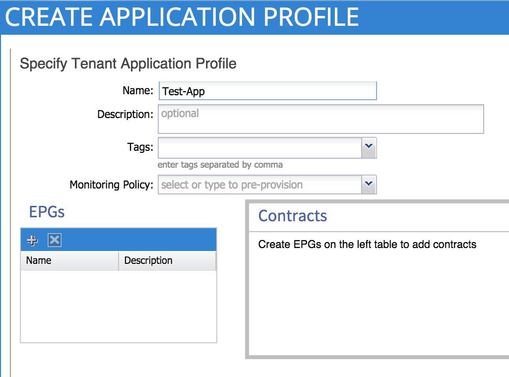
Here, we are creating an application profile called ‘Test-App’. The next step is to create our two EPGs – Web and App. We do this under the application profile that we just created:
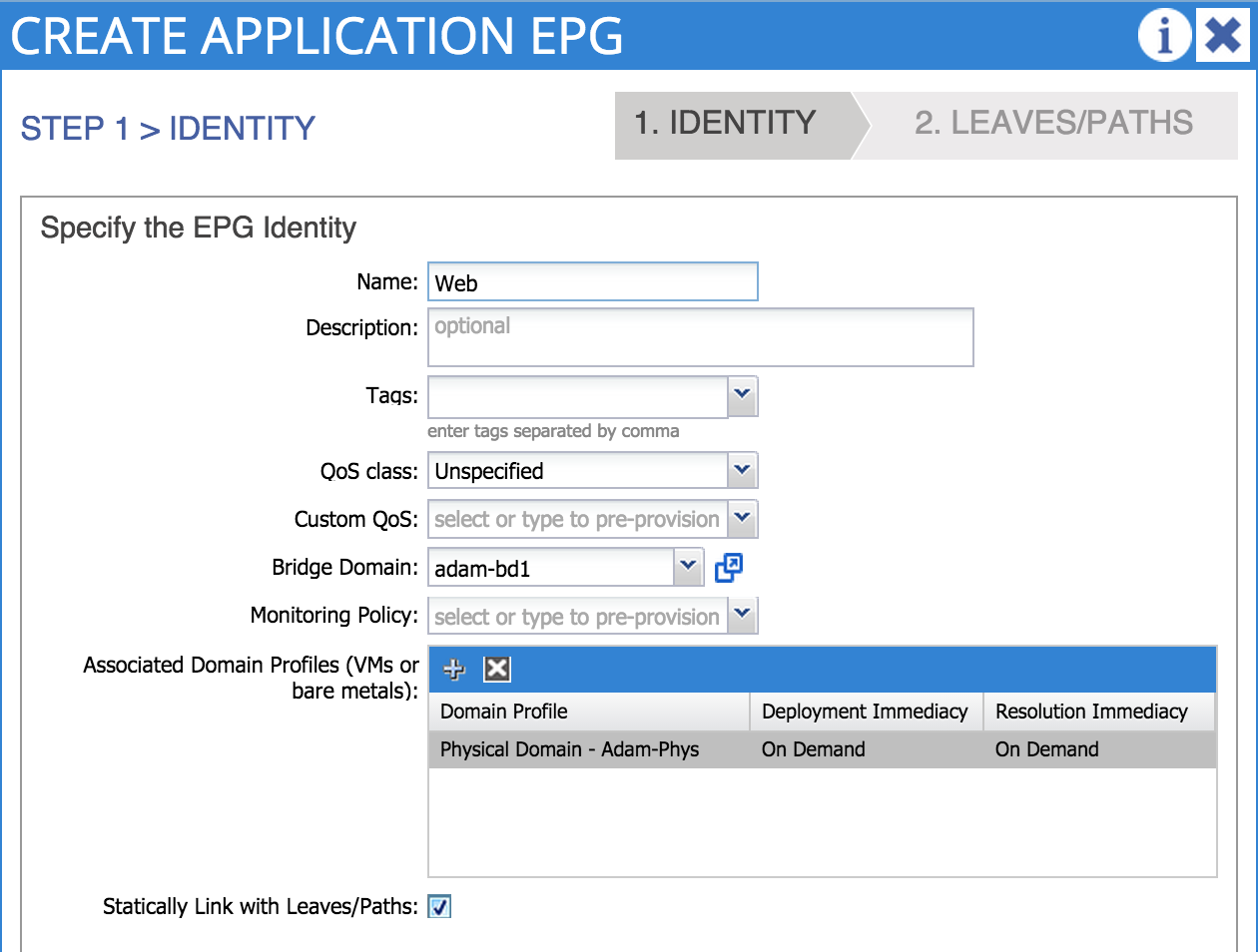
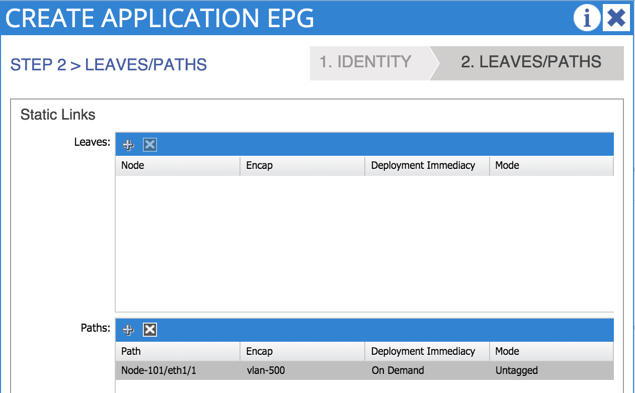
Notice here that I am associating my EPG with a domain - in this case, the physical domain named ‘Adam-Phys’ that I created in part 6. Because we are connecting bare metal hosts to the fabric, we are going to select ‘create static path binding’. A static path binding is simply a way of manually specifying a switch port and VLAN that will be associated with our EPG. Because we have selected this option, an additional screen will become available to us where we must specify the port and VLAN – remember that the VLAN you choose here must fall within the VLAN range that you enabled on the port during the access policy configuration:
We can now see the two EPGs that we have just configured:
At this point, if everything has been configured properly, you should be able to ping the default gateway (the gateway address configured under the bridge domain) from both of your hosts. Note however at this point that no communication should be possible between the two hosts – in order for that to happen we will need to configure some filters and contracts.
Let’s say we want to allow ICMP traffic between host A and host B. We’ll start off by configuring a filter named icmp – this filter will simply specify ICMP traffic:

Now that we have a filter, the next step is to configure a contract – we’ll name this contract _web-to-app _and refer to the ‘icmp’ filter we created a second ago:
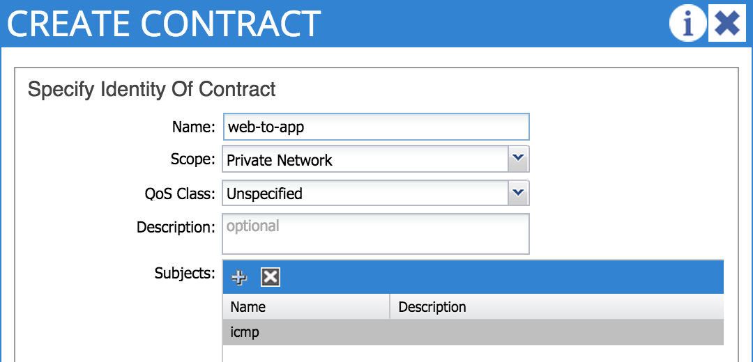
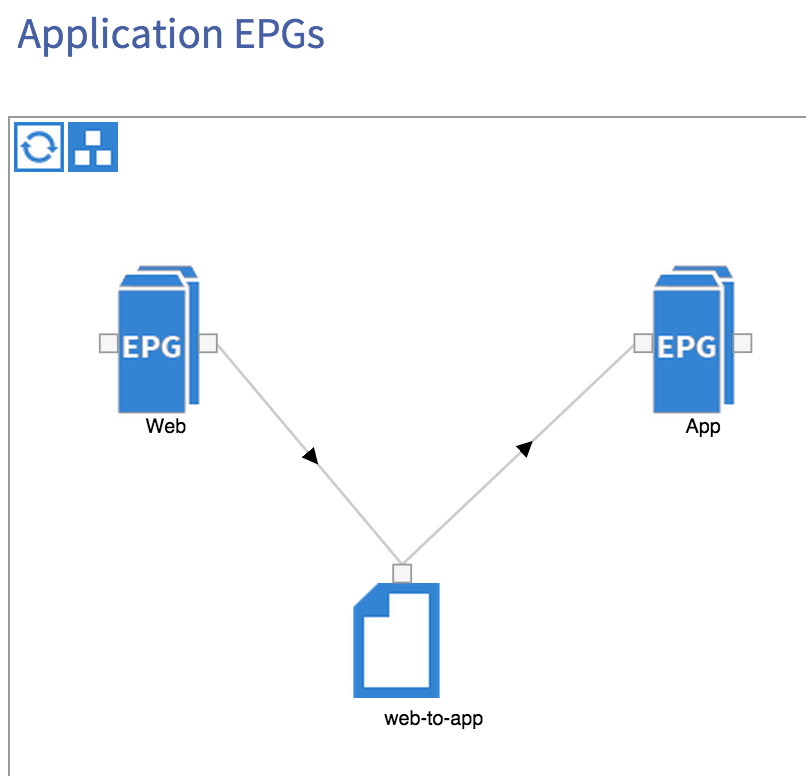
OK, so we have a filter and a contract – what we haven’t done yet however is apply these to any EPG. As you can see from the diagram at the beginning of this post, the Web EPG will provide the web-to-app contract, while the App EPG will consume the same contract. This creates a relationship between the two EPGs and will allow communication between them:
Once we have the contract in place, we should now be able to ping between our two hosts. Obviously this is a very basic example – it’s possible to use much more complex filter entries, with EPGs providing and consuming multiple contracts, service graphs, etc, but hopefully this post has given you an idea of how easy it is to set up application policies within ACI.
In the next post, I’ll take a look at how we can integrate ACI with the server virtualisation layer (specifically vSphere in this case) and how this makes things easier by automatically mapping EPGs to port groups and VLANs.
Thanks for reading!
04 Feb 2015
Just a quick note to say that both my ACI sessions from Cisco Live Milan in January are available now for viewing online:
BRKACI-2345 - ACI: What We Have Learnt From Early Deployments
BRKACI-1789 - How To Perform Common Tasks In ACI
You’ll need a login to access both the slides and the videos.
Enjoy!
Adam